the12volt.com spacer
icon

rs 1000 in 2001 chevrolet silverado


Post ReplyPost New Topic
< Prev Topic Next Topic >
jrilla 
Gold - Posts: 1,498
Gold spaceThis member has made a donation to the12volt.com. Click here for more info.spacespace
Joined: November 19, 2002
Location: North Dakota, United States
Posted: December 13, 2008 at 4:41 PM / IP Logged  
I have to say this. I just realized it has been six years since I found this site, and I don't visit as often as I did when I first started, but when I saw the passlock bypass diagram you posted, I had a good, loud laugh and I had to let you know that I drew that diagram back when I first found this site, and I posted on this free webserver site and I can't believe anyone ever found it.
Good luck with the install.
bertleaf 
Member - Posts: 20
Member spacespace
Joined: November 21, 2008
Location: Alabama, United States
Posted: December 13, 2008 at 5:44 PM / IP Logged  
joch1314 wrote:
ChrisWallace187 pretty much has you taken care of, but one thing i'd like to chime in with is the concealing of the brain.  I'm not sure how big your alarm brain is, but in those vehicles I like mounting the brain behind the very left a/c vent.  The vent is together with the light switch and dimmer and that whole piece just pops out.  Once you get that out there is plenty of room to place your brain.  I just did a 2000 GMC sierra(same truck) two days ago and it was a breeze.  Really easy to route your wires to the ignition harness too.  One thing that i found odd was the starter wire....most starter wires are the same gauge as the other ignition wires but the yellow starter wire in this case was like 18 gauge. 
Thanks for that, and ChrisWallace187 has indeed been a great help.
I frequently see installs mentioning that the brain is behind the instrument cluster, ChrisWallace187 mentioned that place as well but this brain won't fit there especially once all the harnesses are plugged in and I haven't checked behind the Hvac for sure but I don't recall the space behind there being deep or high enough. So I will check out the space behind the vent like you said.
joch1314 wrote:
Also, you'll see two wires in yellow loom plugged in the bottom of the steering column.
Are these positive or negative trigger? Should put them on a time delay and it's sure to surprise any would-be thief.
bertleaf 
Member - Posts: 20
Member spacespace
Joined: November 21, 2008
Location: Alabama, United States
Posted: December 13, 2008 at 5:50 PM / IP Logged  
jrilla wrote:
I have to say this. I just realized it has been six years since I found this site, and I don't visit as often as I did when I first started, but when I saw the passlock bypass diagram you posted, I had a good, loud laugh and I had to let you know that I drew that diagram back when I first found this site, and I posted on this free webserver site and I can't believe anyone ever found it.
Good luck with the install.
That is funny. I'm not even sure where I got that from, I saved it on my computer a few weeks ago.
Well it has certainly been a helpful diagram for me and you can feel good knowing your work from years ago is still helping new guys like me.
joch1314 
Copper - Posts: 301
Copper spacespace
Joined: March 25, 2008
Location: Texas, United States
Posted: December 13, 2008 at 5:53 PM / IP Logged  
not sure...but i think they'll probably be positive trigger. 
...half of the truth can be worse than a lie. <----Roger Russell said that..
bertleaf 
Member - Posts: 20
Member spacespace
Joined: November 21, 2008
Location: Alabama, United States
Posted: December 14, 2008 at 5:10 PM / IP Logged  
Yeah.... I'll just stay away from them. Thanks for the heads-up.
Well I didn't get too much done on the r/s install but I mounted most of the components and got through the firewall and ran all the wires and some cables for an amp so by the time I had that done and out of the way I was out of time as I had other things planned so I will continue another weekend. In the meantime I would just like to get cleared up on most of the connections.
So as usual I have a few questions again:
1. Since I'm not going to use the factory rearm, I'd like to use H10/8 as the horn output so that it also sounds when the alarm is triggered. The wire supplies a transistorized low current output, and should only be connected to the low current ground output from the vehicle's horn switch. So can I connect it to the black wire in the brown plug at the BCM?
2. Is it best to hook up as tachometer check, timer check, or volt check to see if engine is running?
3. In the programing guide there is something mentioned about passive or active arming. I'm not sure what that means.
another-kelly 
Silver - Posts: 618
Silver spacespace
Joined: July 11, 2004
Location: United States
Posted: December 14, 2008 at 8:18 PM / IP Logged  
1) yes
2) tachometer
3) active - arms with remote only
   passive - arms with remote OR arms after (x) amount of time after the alarm sees the last door shut automatically
bertleaf 
Member - Posts: 20
Member spacespace
Joined: November 21, 2008
Location: Alabama, United States
Posted: December 30, 2008 at 5:39 PM / IP Logged  

Thanks another-kelly.

I've got some more time this week so I'm back at it.

H2/1 - RED / white wire - This wire is the input to the flashing parking light relay.  The connection of the this wire will determine the output polarity of the flashing light relay.  IF the vehicle has +12v switched parking lights, you don't need to connect this wire as it is already connected to a +12v source.  If the parking lights are ground switched, cut the wire and connect it to chassis ground.

H2/2 - white wire - (+12V 10A output) - connect this wire to the parking light wire coming from the headlight switch.  do not connect it to the dashboard lighting dimmer switch as the dimmer will be damaged.  The limitation of this wire is 10 amp max, do not exceed this limit or damage to the alarm and parking relay will result.

1) The way I understand this vehicle has +12v switched parking lights at the brown wire in the light blue plug at the BCM.  Can I connect the white wire to the brown wire at the BCM?  It shouldn't ever pull 10amps from there?

2) Since they are positive switched parking lights I suppose I leave the RED / white wire connected to the red wire and hook it up to a constant +12V.

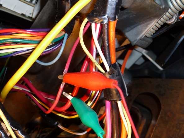
3) Speaking of constant +12v, when I was connecting H1 to the ignition wires, I found only one thick red wire, I tested ti with a DMM and it is constant +12, but I need two, I did see a thin red wire and tested it and it also had +12v with the ignition off and key removed.  So is this the second +12v wire(the one with the red clip)?  I just wasn't sure because it was a smaller wire compared to the other one(with the green clip) and compared to the wire it connects to in H1.

4) Can I connect all the wires that need +12v all the time to the red ignition wires?  Probably to the bigger one?

rs 1000 in 2001 chevrolet silverado - Page 3 -- posted image.

Thanks

joch1314 
Copper - Posts: 301
Copper spacespace
Joined: March 25, 2008
Location: Texas, United States
Posted: December 30, 2008 at 6:25 PM / IP Logged  
I think that the RED / white wire also has 12V+ constant...Try testing that, but i don't see any problems hooking other wires (as long as they're not thicker gauge remote start wires) to the red wire you mentioned.  Why not get the parking light wire at the switch...it should be light blue (+).  Make sure you hook up both ignition wires (pink and white).
...half of the truth can be worse than a lie. <----Roger Russell said that..
bertleaf 
Member - Posts: 20
Member spacespace
Joined: November 21, 2008
Location: Alabama, United States
Posted: December 30, 2008 at 8:09 PM / IP Logged  

Thanks joch1314.

I did check the fat RED / white but I didn't get anything, I'll try agian tomorrow, maybe I misssed.

The reason I wondered about hooking the parking wire at the BCM is because I thought it might be easier and I wouldn't have to worry about how much current it draws but I suposse the switch is right where I am working and I could always use a fuse.

chriswallace187 
Gold - Posts: 1,661
Gold spacespace
Joined: March 11, 2002
Location: Pennsylvania, United States
Posted: December 30, 2008 at 10:11 PM / IP Logged  

The brown wire will draw the same current whether or not you connect it at the BCM or the switch - I think the only reason it goes to the BCM is as a signal input for the "lights-on" reminder chimes and such. 

Unless your truck's got extra lighting (running boards, cab markers, etc.) or a trailer connector wired directly to that parking light circuit (I believe that '99-up Silverado has a separate fuse for the factory trailer wiring), you should be allright with the direct connection.

If it blows the fuse on the RED / white, you can always put in a relay for the parking lights.  The angry warning about relay/control module damage only applies to idiots who blow that 10A fuse and then replace it with a 20A instead of wiring in a relay - and you don't strike me as the type :-).

Also I agree with joch1314 on the RED / white at the harness being 12V constant.  Basically all GM vehicles with heavy gauge ign. switch wires have red and RED / white, or 2 separate red as their constant 12V feeds.

C Renner's Auto Electronix
My service is cheap, quick, and good - pick any two
Page of 4

  Printable version Printable version Post ReplyPost New Topic
You cannot post new topics in this forum
You cannot reply to topics in this forum
You cannot delete your posts in this forum
You cannot edit your posts in this forum
You cannot create polls in this forum
You cannot vote in polls in this forum

  •  
Search the12volt.com
Follow the12volt.com Follow the12volt.com on Facebook
Saturday, April 20, 2024 • Copyright © 1999-2024 the12volt.com, All Rights Reserved Privacy Policy & Use of Cookies
Disclaimer: *All information on this site ( the12volt.com ) is provided "as is" without any warranty of any kind, either expressed or implied, including but not limited to fitness for a particular use. Any user assumes the entire risk as to the accuracy and use of this information. Please verify all wire colors and diagrams before applying any information.

Secured by Sectigo
the12volt.com spacer
Support the12volt.com
Top
the12volt.com spacer