the12volt.com spacer
icon

97 accord ex 2 stage door unlock


Post ReplyPost New Topic
< Prev Topic Next Topic >
smorton 
Member - Posts: 9
Member spacespace
Joined: December 12, 2008
Location: Arizona, United States
Posted: December 12, 2008 at 7:25 PM / IP Logged  

Hi!

I am installing the Astra 600 in a 1997 Honda Accord EX Sedan (VTech, 4 cylinder, A/T) and am at the point where I want to connect the blue wire from the alarm door lock/unlock bundle for a 2-Stage door unlock. Per the instrucions (page 17), I have the relay and 15 amp fuse, but I am unable to determine if there is a wire under the dash that I can use for the unlock signal (blue wire). This is the wire that will be cut and the relay connected to. Per the Hanes manual, the wire should be BLACK/ Red, but I suspect that it is located in the drivers door. I would prefer not to try to route a wire through the harness to the door, but if that's the only (and/or best) way, then I will do it. Can anyone please confirm the wire color and best wire location for this setup?

Thanks!!

Scott

tedmond 
Gold - Posts: 4,610
Gold spaceThis member has been recognized as an authority in Mobile Security and Convenience. Click here for more info.spacespace
Joined: January 06, 2007
Location: Ontario, Canada
Posted: December 12, 2008 at 7:55 PM / IP Logged  

Power unlock - orange (-) DKP in grey plug

Power lock - BLACK/ white (-) DKP in grey plug

if you want driver priority unlock, you need to wire the relay in the door and tag the lock actuator wires.

smorton 
Member - Posts: 9
Member spacespace
Joined: December 12, 2008
Location: Arizona, United States
Posted: December 12, 2008 at 8:05 PM / IP Logged  

Thank you!

The instructions call it 2-Stage Door Lock/Unlock, but I guess it is also called driver priority unlock.  That is what I trying to connect. Looks like I have to take the door apart as well. Can you confirm the wire color coming at the servo connector? Any tips on where to place the relay in the door or which wire to use to power the relay?

Thanks!

Scott

tedmond 
Gold - Posts: 4,610
Gold spaceThis member has been recognized as an authority in Mobile Security and Convenience. Click here for more info.spacespace
Joined: January 06, 2007
Location: Ontario, Canada
Posted: December 12, 2008 at 9:58 PM / IP Logged  

the wires are located in the door, and its impossible to miss. just look for 2 wires going to the lock motor. one will be 12v and the onther will show ground(-) when the switch at the door is pressed. just power the relay with any 12v line available. wire it up like so.

since this is a negative trigger lock.

85 - DPU (driver pri unlock) wire from alarm or rs (-)

86 - constant 12v fused @ 5 amps to protect relay
87 - GROUND

CUT THE WIRE THAT CONNECTS SWITCH TO THE LOCK ACTUATOR. connect one end to each terminal

87a - wire that shows ground when switch @ door is pressed (switch side)
30 - lock motor wire (actuator or lock side)

this way you can still get priority and still control that with the door switches.

OR

Follow the diagram given to you ahaha ! cheers

tedmond 
Gold - Posts: 4,610
Gold spaceThis member has been recognized as an authority in Mobile Security and Convenience. Click here for more info.spacespace
Joined: January 06, 2007
Location: Ontario, Canada
Posted: December 12, 2008 at 10:04 PM / IP Logged  
forgot to mention, usually i will place the relay higher up from the door to prevent moisture and i look for an existing bungle of wires and rip tie to down to make sure its solid and in place.
smorton 
Member - Posts: 9
Member spacespace
Joined: December 12, 2008
Location: Arizona, United States
Posted: December 13, 2008 at 9:57 AM / IP Logged  

Thank You!!!

I'll post back as soon as I get everything wired and to let you know how it went.

Scott

smorton 
Member - Posts: 9
Member spacespace
Joined: December 12, 2008
Location: Arizona, United States
Posted: December 13, 2008 at 7:32 PM / IP Logged  
Got the door panel apart, removed the molex and routed the Blue wire from the alarm through the molex and into the door. This took most of the day.
I got the wires hooked up but the drivers door will not unlock when I turn off the alarm. All of the doors lock when I turn on the alarm and all of the doors unlock when I turn off the alarm by pressing twice on the remote off button.
The Hanes manual shows the BLACK/ Red and Pink wires going to the driver's door actuator. These wires where found in the Door Lock Module plug.
These are the voltage measurements from the BLACK/ Red and Pink wires at the Door Lock Module before I made any connections:
            Neutral Position     Lock      Unlock
BLACK/ Red   0V    5.8V      0V
Pink        4.8V 0V        4.8V
Here is how the relay is hooked up:
85 - Blue wire from alarm door lock bundle
86 - 12v fused @ 15 amps. I am using the White wire from the Door Lock Module
87 - GROUND
87a - The BLACK/ Red wire coming from the Door Lock Module (shows 0V when you move the door switch to the unlock position).
30 - The BLACK/ Red wire going to the actuator.
Since the driver's side actuator does not unlock when I turn off the alarm, could I have the 87a and 30 switched or should I use the Pink wire?
Thanks!!
Scott
chriswallace187 
Gold - Posts: 1,661
Gold spacespace
Joined: March 11, 2002
Location: Pennsylvania, United States
Posted: December 14, 2008 at 2:07 AM / IP Logged  
Scott,
What you actually have there are 2 wires peculiar to Hondas. They switch the power locks when the driver's lock is manually moved up and down; however neither one is what you need to connect to in order to have 2-stage unlocking.
I don't have the exact color of the driver's unlock motor wire; perhaps someone can post it who's got access to technical info at the moment.(I do know the later models were yellow or YELLOW /GREEN).
You can find that wire(it should be in the rubber boot full of wires that goes into the door) by using your meter; it will show 12V when pressing the switch to "unlock" and 0V otherwise. Once you've got the suspected wire, cut it. This should result in the driver's door no longer locking or unlocking with the switch, and all other doors continuing to work.
Also to elaborate on what tedmond's said - you'll be using the wire from your alarm that's simply marked "(-) unlock" in order to activate this relay. The "2nd unlock" wire will go to the "orange (-) unlock DKP gray plug" on the car.
C Renner's Auto Electronix
My service is cheap, quick, and good - pick any two
smorton 
Member - Posts: 9
Member spacespace
Joined: December 12, 2008
Location: Arizona, United States
Posted: December 14, 2008 at 5:12 PM / IP Logged  

Hi!

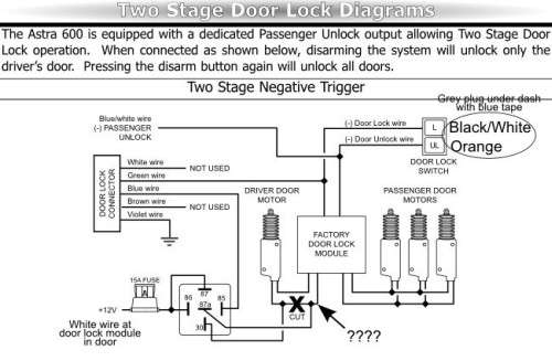
Thank you for the information. I checked the wires again at the factory door lock module and found a Yellow/Red wire that has 12V when in "unlock", 0V in "neutral" and 1.1V in "lock". There is also a WHITE/ Red wire at the module that has the opposite measurements, 1.1V = "unlock", 0V = "neutral" and 12V = "lock".   These two wires are also heaver gauge than the others that go to the actuator. I cut the Yellow/Red wire and all of the door locks would not work, so that one can't be it. I have attached the wiring diagram for 2 Stage Door Locks from the instruction manual:

97 accord ex 2 stage door unlock -- posted image.

I have the relay wired as shown and also tried 87 to Ground with no luck. No other wire I found at the factory module has 12V in "unlock" and 0V in "lock".   Not really sure what else to try. Any suggestons???

Scott

t&t tech 
Platinum - Posts: 2,608
Platinum spacespace
Joined: October 05, 2008
Location: Trinidad and Tobago
Posted: December 14, 2008 at 5:32 PM / IP Logged  
ok lemme try, i've never done priority locking on this vehicle, but i've done other hondas, if you take the actuator wire from the control module it won't work, the only wires bein attached there are the lock, and second unlock trigger wires, then take the unlock wire from the alarm into the driver door panel, there are normally five wires leading to the actuator, two being larger gauge than the other three, those two will be the lock/unlock motor wires, cut the unlock wire, and connect as you have the relay above, except ground terminal 87a, if you have central lockin you'll have to disable this also, the other three wires, one should be black, the other two are the central lock trigger wires, just cut them and isolate them, hope i can help.
commit your way to jehovah and he will act in your behalf. psalms 37:5
Page of 3

  Printable version Printable version Post ReplyPost New Topic
You cannot post new topics in this forum
You cannot reply to topics in this forum
You cannot delete your posts in this forum
You cannot edit your posts in this forum
You cannot create polls in this forum
You cannot vote in polls in this forum

  •  
Search the12volt.com
Follow the12volt.com Follow the12volt.com on Facebook
Sunday, May 19, 2024 • Copyright © 1999-2024 the12volt.com, All Rights Reserved Privacy Policy & Use of Cookies
Disclaimer: *All information on this site ( the12volt.com ) is provided "as is" without any warranty of any kind, either expressed or implied, including but not limited to fitness for a particular use. Any user assumes the entire risk as to the accuracy and use of this information. Please verify all wire colors and diagrams before applying any information.

Secured by Sectigo
the12volt.com spacer
Support the12volt.com
Top
the12volt.com spacer