the12volt.com spacer
icon

2007 toyota tacoma 2.7l remote start.


Post ReplyPost New Topic
< Prev Topic Next Topic >
tacomajason 
Member - Posts: 9
Member spacespace
Joined: January 13, 2009
Location: Arkansas, United States
Posted: January 13, 2009 at 3:09 AM / IP Logged  
hey guys, since this is my first post, and i could not find a intro section, my name is Jason. I have a 2007 Toyota Tacoma 2.7l single cab 4x4.
2007 toyota tacoma 2.7l remote start. -- posted image.
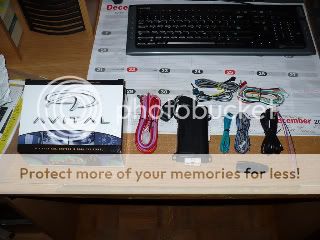
I am an active member at www.customtacos.com, but i am having trouble getting sound advice on my current project. a little christmas present to myself was an avital model 4113 remote start.
2007 toyota tacoma 2.7l remote start. -- posted image.
i am a mechanic by trade, so it's not the physical act of the installation that i am worried about. i would just like to ask a couple questions.
as far as i know, my vehicle is not equipped with a chip in the key. how can i verify that i do not need some sort of immobilizer relay?
the installation guide tells me to refer to www.directtechs.com, but i am not a registered dealer, so i am not allowed access. where can i find a guide telling me where the wires are for this? is there something on this site i can refer to?
i am sure all these questions have been asked before, and i did search, but all i found was information on the "up" model v6 tacoma. thank you in advance guys, i am looking foward to getting this installed, and also learning a thing or two!
Mike M2 
Platinum - Posts: 2,652
Platinum spacespace
Joined: June 29, 2005
Location: United States
Posted: January 13, 2009 at 6:20 AM / IP Logged  

The standard cab doesn't have an immobilizer so you are correct there. Wiring is the same for all models, look here

12 VOLTS WHITE/ blue Ignition switch harness   + 
 IGNITION Blue / YELLOW Ignition switch harness   + 
 IGNITION 2 BLACK/ red Ignition switch harness   + 
 ACCESSORY Runs with ignition wire     
 STARTER BLACK/ white Ignition switch harness   + 
 STARTER 2 GREEN/ black Ignition switch harness   + 
 KEY SENSE GREEN/ black Ignition switch   - 
 TACH SIGNAL BLACK/ white At diagnostic plug below driver's side dash   AC 
 FUEL INJECTOR Opposite from BLACK/ red At any injector on engine   AC 
 LOCK Violet On white connector in driver's kickpanel   - 
 UNLOCK GREEN/ black (double pulses) On white connector in driver's kickpanel   - 
 DOORPIN GREEN / WHITE In 26-pin plug on module connected to fusebox under dash   - 
 FACTORY ARM Arms with lock wire     
 FACTORY DISARM Disarms with unlock wire     
 BRAKESWITCH Blue At switch above brake pedal   + 
 PARKLIGHTS Green In 13-pin plug on left of fuses on fusebox under dash   + 
 PARKLIGHTS (-) Green Light switch harness   - 
 HAND BRAKE GREEN / WHITE At switch on handbrake lever   - 
 HORN GREEN/ red In 13-pin plug at right of fuses on fusebox under dash   - 
 CLUTCH SWITCH BLACK/ white At switch on top of clutch pedal   TYPE 1 
 DRIVER WINDOW UP Blue / YELLOW At master window switch   REV POL 
 DRIVER WINDOW DOWN Blue/green At master window switch   REV POL 
 PASSENGER WINDOW UP RED / black At master window switch   REV POL 
 PASSENGER WINDOW DOWN RED / green At master window switch   REV POL 
 HEADLIGHTS RED / blue or RED / green At light switch harness   - 
 REVERSE LIGHTS RED / black In driver's kickpanel   + 
 DIMMER WHITE/ green At harness behind dimmer switch   + 
 VSS WIRE GREEN/ orange At ECM behind glovebox  

Mike M2
Tech Manager
CS Dealer Services
Chris Luongo 
Platinum - Posts: 3,746
Platinum spaceThis member consistently provides reliable informationspace
Joined: May 21, 2002
Location: Massachusetts, United States
Posted: January 13, 2009 at 7:00 AM / IP Logged  
To double-check that you don't have an immobilizer key:
1. Sit in vehicle, with engine off, ignition key removed.
2. Just below the radio, there's a panel with the clock, the passenger airbag light, and maybe some buttons to set the clock too.
3. Verify that there is NOT a flashing red light in that panel.
WIRING;
Use that chart for the wire colors, but you can usually find better locations for the wires, to make things easier.
Ignition wires: You don't even have to unfasten the cover from the steering column. Once you get the dash off, you'll see the heavy harness coming down, then going off to the left.
Brake and parking lights: Brake, and positive lights, are together in the left-most plug at the driver's fuse box.
Locks: After removing the driver's kick panel, it's not hard to figure out which wire bundle is coming in from the driver's door (Just reach into the doorjamb and wiggle the rubber boot, while watching inside.)
The driver's door harness has two separate bundles, taped together. Your lock wires are in the smaller of the two bundles, the one that does NOT contain the larger wires.
P.S. Factory Toyota remotes don't work with the car running. Even if you have factory keyless, it won't let you in when the remote starter is on.
Tach: Just below the fuses, in the OBDII mechanic's diagnostic plug. Apply the parking brake to get the pedal out of the way, snap out the plug, let it hang down, and you'll have just enough slack to work.
DISASSEMBLY:
1. Just below and to the right of the ignition key, depending on where your parking brake is......either snap out the change pocket, or pry off the little trim plate around the parking brake handle.
2. On driver's side floor, pry off "dead pedal" (footrest), unscrew little plastic "hand nut" behind.
3. Pry off driver's doorsill panel. It's brittle when cold; leave truck running with heater on before starting.
4. Remove driver's kick panel by sliding backward, going slowly so you can realize where it's clipped on to try not to break it.
5. Behind where that kick panel was, remove one 10mm bolt.
6. Going back to the right, below where the change pocket/emergency brake is, open that little "flap," undo one more 10mm bolt.
7. Pull entire dash panel backward, it'll come off. Undo all wiring plugs, and hood release cable.
8. You'll see a small black metal plate, partially blocking your ignition wires. Undo three 10mm bolts, remove black panel.
REMOTE START BRAIN LOCATION:
Seeing as it's only a remote starter, and not an alarm, I see no need to hide it.
Just to the left of the brake pedal assembly, there's a little room there. I would secure it to the brake pedal assembly with a few zip ties. Then, it's very easy to access in the future for any repairs. But make sure you put it in a way that it can't interfere with any of the pedals.
tacomajason 
Member - Posts: 9
Member spacespace
Joined: January 13, 2009
Location: Arkansas, United States
Posted: January 13, 2009 at 11:03 AM / IP Logged  
wow, that list of wires and their locations is just what i need! i guess i failed to mention that i have manual locks and windows, so i assume i will just cap those wires and not worry about them.
the following wires ask for 30 amps all positive
output to ignition circuit
output to starter circuit
output to accessory circuit
high current 12 input
high current 12v input
i assume that these are going to be found in the engine bay. can you guys shed any light on this?
jrod83 
Copper - Posts: 81
Copper spacespace
Joined: October 29, 2007
Location: Texas, United States
Posted: January 13, 2009 at 11:17 AM / IP Logged  
all those wires are in the ignition column......match thos wires to the tech sheet that was posted above....if you look to the right of the wire colors on the tech sheet it will tell you the location of the wire....
MECP Certified
I am the loudest and proudest member of the Fighting Aggies Class of '11 WHOOP!
SAW 'EM OFF!
jrod83 
Copper - Posts: 81
Copper spacespace
Joined: October 29, 2007
Location: Texas, United States
Posted: January 13, 2009 at 11:18 AM / IP Logged  

since you put it that way this is all you would need

12 VOLTS WHITE/ blue Ignition switch harness   + 
 IGNITION Blue / YELLOW Ignition switch harness   + 
 IGNITION 2 BLACK/ red Ignition switch harness   + 
 ACCESSORY Runs with ignition wire     
 STARTER BLACK/ white Ignition switch harness   + 
 STARTER 2 GREEN/ black Ignition switch harness   + 
 KEY SENSE GREEN/ black Ignition switch   - 
 TACH SIGNAL BLACK/ white At diagnostic plug below driver's side dash   AC 

MECP Certified
I am the loudest and proudest member of the Fighting Aggies Class of '11 WHOOP!
SAW 'EM OFF!
tacomajason 
Member - Posts: 9
Member spacespace
Joined: January 13, 2009
Location: Arkansas, United States
Posted: January 13, 2009 at 11:45 AM / IP Logged  
and as for the wire i have marked for "light flash". should i tap into
PARKLIGHTS       Green       In 13-pin plug on left of fuses on fusebox under dash ?
jrod83 
Copper - Posts: 81
Copper spacespace
Joined: October 29, 2007
Location: Texas, United States
Posted: January 13, 2009 at 11:56 AM / IP Logged  
oh yeah sry bout that...but yeah thats what you do...i dont think you would need the keysense either...
MECP Certified
I am the loudest and proudest member of the Fighting Aggies Class of '11 WHOOP!
SAW 'EM OFF!
tacomajason 
Member - Posts: 9
Member spacespace
Joined: January 13, 2009
Location: Arkansas, United States
Posted: January 13, 2009 at 1:04 PM / IP Logged  
jrod83 wrote:

since you put it that way this is all you would need

<TABLE id=ppp style="MARGIN-TOP: 5px" cellSpacing=0 cellPadding=2 width="100%">
<T>
<TR>
<TD style="FONT-WEIGHT: bold">12 VOLTS</TD>
<TD> WHITE/ blue</TD>
<TD> Ignition switch harness  </TD>
<TD align=middle> + </TD></TR>
<TR>
<TD style="FONT-WEIGHT: bold"> IGNITION</TD>
<TD> Blue / YELLOW</TD>
<TD> Ignition switch harness  </TD>
<TD align=middle> + </TD></TR>
<TR>
<TD style="FONT-WEIGHT: bold"> IGNITION 2</TD>
<TD> BLACK/ red</TD>
<TD> Ignition switch harness  </TD>
<TD align=middle> + </TD></TR>
<TR>
<TD style="FONT-WEIGHT: bold"> ACCESSORY</TD>
<TD> Runs with ignition wire</TD>
<TD>   </TD>
<TD align=middle>  </TD></TR>
<TR>
<TD style="FONT-WEIGHT: bold"> STARTER</TD>
<TD> BLACK/ white</TD>
<TD> Ignition switch harness  </TD>
<TD align=middle> + </TD></TR>
<TR>
<TD style="FONT-WEIGHT: bold"> STARTER 2</TD>
<TD> GREEN/ black</TD>
<TD> Ignition switch harness  </TD>
<TD align=middle> + </TD></TR>
<TR>
<TD style="FONT-WEIGHT: bold"> KEY SENSE</TD>
<TD> GREEN/ black</TD>
<TD> Ignition switch  </TD>
<TD align=middle> - </TD></TR>
<TR>
<TD style="FONT-WEIGHT: bold"> TACH SIGNAL</TD>
<TD> BLACK/ white</TD>
<TD> At diagnostic plug below driver's side dash  </TD>
<TD align=middle> AC </TD></TR></T></TABLE>

ok this is good news, since this is only half of the wires listed.just to verify i will list the wires you are saying i don't need
factory alarm disarm
factory rearm
(+)ignition out(to alarm)
(-)activation input
(-)horn output
ground (i think i will need this, and i have some more questions about grounding)
status output
(-)accessory output
(-)starter output
(-)starter output
(+)brake switch shutdown wire
(-)neutral safety switch input
(-)hood pinswitch shutdown wire
this is just list of wires this thing has minus the ones you said i need.
i plan on grounding out a couple of the safety features. the neutral saftey switch input, and the hood pinswitch shutdown wire. can these go to the same ground that the black ground wire goes to, or should i find a different location.
tacomajason 
Member - Posts: 9
Member spacespace
Joined: January 13, 2009
Location: Arkansas, United States
Posted: January 13, 2009 at 1:25 PM / IP Logged  
i got into my ignition/steering column and i found a few wires that have the same colors. i took a picture, and it's a little bit larger then the recommended size, but you cant see what i am talking about with it any smaller
2007 toyota tacoma 2.7l remote start. -- posted image.
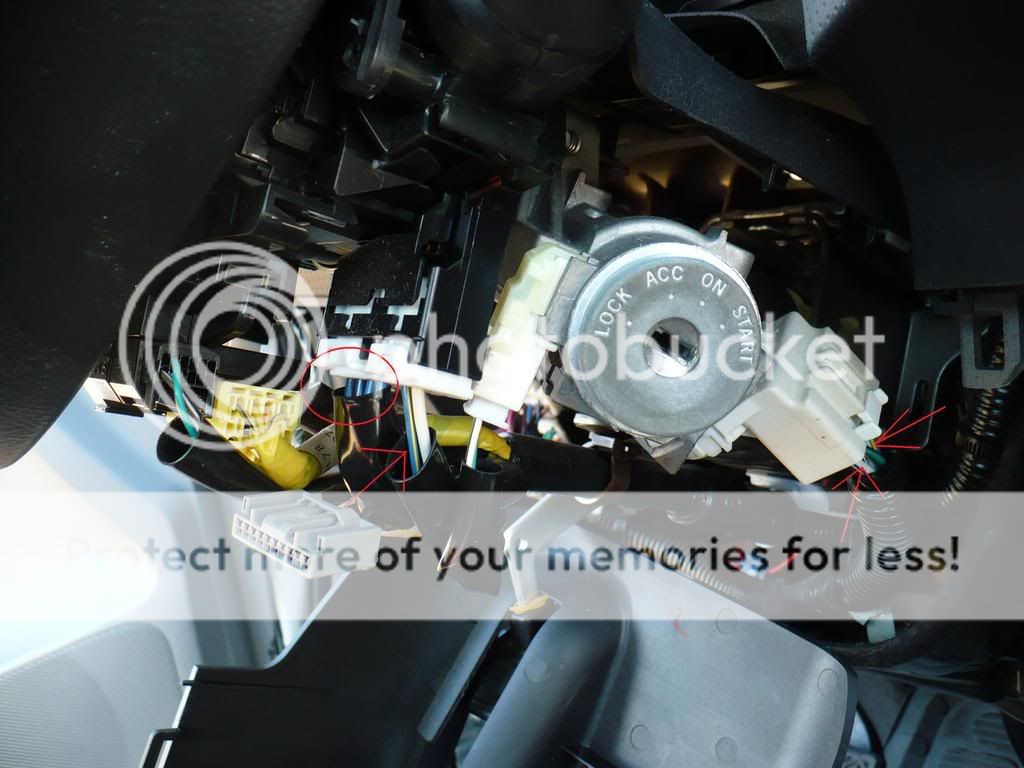
the wires to the left go up into my wiper stalk, but the are the same guage as the ones to the right, so i thought i would ask (they seem to be pretty heavy duty for wipers) also the little harness coming off the left side of the ignition switch has a white wire with a black stripe. is this my starter wire?
Page of 3

  Printable version Printable version Post ReplyPost New Topic
You cannot post new topics in this forum
You cannot reply to topics in this forum
You cannot delete your posts in this forum
You cannot edit your posts in this forum
You cannot create polls in this forum
You cannot vote in polls in this forum

  •  
Search the12volt.com
Follow the12volt.com Follow the12volt.com on Facebook
Thursday, March 28, 2024 • Copyright © 1999-2024 the12volt.com, All Rights Reserved Privacy Policy & Use of Cookies
Disclaimer: *All information on this site ( the12volt.com ) is provided "as is" without any warranty of any kind, either expressed or implied, including but not limited to fitness for a particular use. Any user assumes the entire risk as to the accuracy and use of this information. Please verify all wire colors and diagrams before applying any information.

Secured by Sectigo
the12volt.com spacer
Support the12volt.com
Top
the12volt.com spacer