the12volt.com spacer
icon

temperature displays


Post ReplyPost New Topic
< Prev Topic Next Topic >
bigjohnny 
Copper - Posts: 293
Copper spacespace
Joined: September 23, 2008
Location: Ontario, Canada
Posted: July 17, 2009 at 11:58 PM / IP Logged  
here is what the final circuit will look like I believe.
This provides me 3x 5 volt outputs to power the 2 temp displays, and the voltage meter, and an isolated 5v output to power the amperage meter, effectively isolating the voltage/current meters from each other.
The voltage meter will have an isolator on it's measure input, so both meters will also be measuring from an isolated source.
I don't know if the symbol for the isolators i'm using is correct, but for the purposes of this diagram it will work, the correct part number is shown.
I was looking at freepcb, I'm not quite sure how to use it, so it's gonna take a little time to learn, I'll probably just end up using the board that idiot mentioned above.
any suggestions for particular part placement on the mentioned perf board?
temperature displays - Page 8 -- posted image.
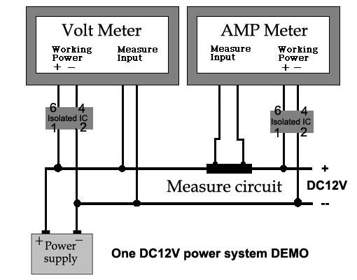
Here is how the two meters will basically be wired up
temperature displays - Page 8 -- posted image.
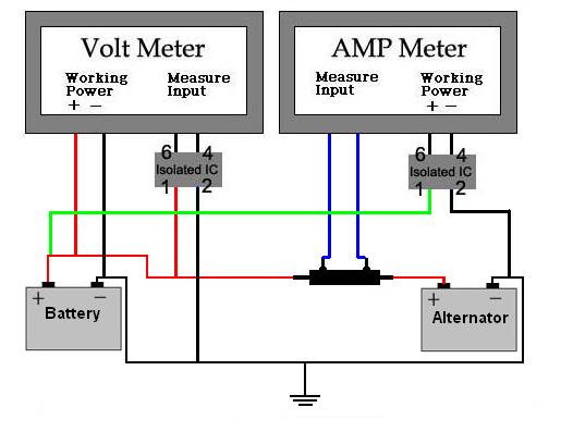
And the diagram of how the company says both meters should be wired with isolators, which totally contradicts what is said on the original diagram sent with these units.
temperature displays - Page 8 -- posted image.
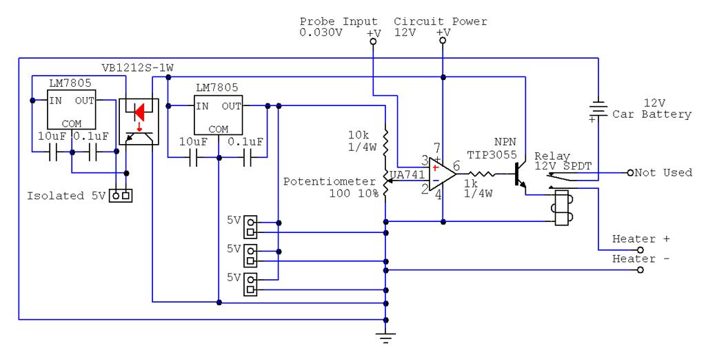
And this is the original diagram sent with the meters
temperature displays - Page 8 -- posted image.
i am an idiot 
Platinum - Posts: 13,667
Platinum spaceThis member consistently provides reliable informationspace
Joined: September 21, 2006
Location: Louisiana, United States
Posted: July 19, 2009 at 9:51 PM / IP Logged  
I would recommend connecting the heater negative wire directly to ground.  It will take a huge trace on the circuit board if you connect it to the board.
Let's Go Brandon Brown. Congratulations on your first Xfinity Series Win. LGBFJB
bigjohnny 
Copper - Posts: 293
Copper spacespace
Joined: September 23, 2008
Location: Ontario, Canada
Posted: July 20, 2009 at 7:26 AM / IP Logged  
it wouldn't be connected to the board, I can't believe I did that, but it was more for a reference I thought I had shown it connected directly to ground.
but yeah, that wouldn't really be a smart thing to do.
bigjohnny 
Copper - Posts: 293
Copper spacespace
Joined: September 23, 2008
Location: Ontario, Canada
Posted: July 21, 2009 at 7:38 AM / IP Logged  
I'm unable to order one of the perf boards from radio shack because they don't have an option for shipping to Canada.
so where can I find a board to solder my stuff onto that will ship to Canada, the only stuff I can find locally is either huge, or simply the wrong layout.
bigjohnny 
Copper - Posts: 293
Copper spacespace
Joined: September 23, 2008
Location: Ontario, Canada
Posted: July 24, 2009 at 6:59 PM / IP Logged  
Well, I got this circuit built, haven't had a chance to fully test it as I haven't yet connected the temp probe, but the isolated circuit is producing 5v, the transistor has 12v output on pin 3, and except for putting the first isolator in backwards, appears to be working now. I just have to find some 2pin connectors of some sort, and put some finishing touches on the circuit before I can use it, and it might have to wait until next payday (3 weeks...ugh)
HOWEVER I now have to find another one of these damn isolators.
The info on the part is
"YAOHUA DY 12S12-1W" And I believe it's a DC-DC Isolated power supply or DC-DC Converter.
By mistake I had been looking up VB1212S-1W and it turns out this is a part also, and appears to be the exact same damn thing, I can't figure out what the differences are so I'm wondering if it's a number that's been cross referenced by pure coincidence.
Either way I need another one of these damn things, and I don't want to have to order one from the Asian seller I have been getting these meters/parts from.
How can I get some info on this damn thing because there is a good chance my local shop carries a similar part if I just knew what exactly this DY 12S12-1W was/is.
KPierson 
Platinum - Posts: 3,527
Platinum spaceThis member consistently provides reliable informationspace
Joined: April 14, 2005
Location: Ohio, United States
Posted: July 24, 2009 at 8:26 PM / IP Logged  

Check out this:

Murata NKE1212SC

It's a 1 watt isolated 12vdc to 12vdc power supply available through digikey.

Kevin Pierson
bigjohnny 
Copper - Posts: 293
Copper spacespace
Joined: September 23, 2008
Location: Ontario, Canada
Posted: July 24, 2009 at 9:31 PM / IP Logged  
I'll look into that... I also just realized I said damn 3 times in the previous post all of which referring to the isolators.... If I could edit that post I would edit those out, I didn't even realize I had done that.
From the price of those I might be better off getting them from the Asian guy, as he is selling me stuff at cost, and these are only $6.99USD through him, and at this point I've already spent about $100 or so between the meters, and various parts.
I've been having bad luck with burning things out...
EDIT AGAIN
He is going to send me another one, free. You know, I really cant say enough good things about this guy, he has great customer service, and some very interesting products. The seller is "giorgio11185", and his eBay store is "Asia Engineer"
I suggest if your looking for meters like the ones mentioned in this thread, to definitely check this guy out.
bigjohnny 
Copper - Posts: 293
Copper spacespace
Joined: September 23, 2008
Location: Ontario, Canada
Posted: July 26, 2009 at 5:44 PM / IP Logged  
I have a couple of questions about the potentiometer, I think I may have gotten the pins wrong.
The pot that I got is a 201UR101B, their is no pin data in the datasheet. Is pin 1 and 2 the ones that are side by side, and pin 3 is the one in the middle?
or are 1 and 3 the side by side ones.?
in the diagram, is the "ground"(the middle) the one which is connected to pin 2 of the op-amp?
transistor pin 2 gets 12v power?
op-amp pin 2 gets 12v power?
i am an idiot 
Platinum - Posts: 13,667
Platinum spaceThis member consistently provides reliable informationspace
Joined: September 21, 2006
Location: Louisiana, United States
Posted: July 26, 2009 at 6:01 PM / IP Logged  
The center pin on the diagram is known as the wiper.  If it is a 1K potentiometer there are 2 pins that will always have 1K ohm across them, no matter the position of the wiper.  Set the pot to the middle, using your meter find the 2 pins that read 1K.  these 2 are the outside connections of the pot.  Pot out of the circuit for testing.
Let's Go Brandon Brown. Congratulations on your first Xfinity Series Win. LGBFJB
bigjohnny 
Copper - Posts: 293
Copper spacespace
Joined: September 23, 2008
Location: Ontario, Canada
Posted: July 27, 2009 at 7:03 PM / IP Logged  
ok, I was looking for some assistance on getting a gerber file made up for the circuit so I could get a PCB made (or make one myself) and was asking around on an electronics forum, now they are telling me this circuit is basically all wrong.
I know it is a little inefficient since I don't do a lot of this stuff, and I've had to use extra parts to work with parts I already have (2x 7805's for each DC-DC converter so I have 5v, where if I BUY new ones I can get 12v/5v and reduce the number of parts) I'm sure I can reduce the amount of caps also. Perhaps just using the 1000uF cap I have to filter the entire circuit, instead of filtering each individual sub-curcuit.
they say the 741 op-amp won't even work with such a low voltage, (1.97v less than the 741 needs to operate) and since I'm using it as a comparator.
The changes I made are reflected in the following diagram, their comments below.
temperature displays - Page 8 -- posted image.
Sch3mat1c wrote:
The 7812 won't do its job, it needs 15V or more. And you need protection stuff (forward diode, TVS and big 'lytic are a good combination) because automotive 12V is only 12V on average.
The 741 won't do whatever the heck you think it's going to do. Whatever "probe" is, 0.03V is 1.97V below anything the 741 can see. Use an LM358, which includes 0V. But since you appear to be using it as a comparator, that will still be awful. So use an LM393, which is a comparator, and a pull-up resistor on the output. But you show a 2N3055 emitter follower driving a relay, which is just silly. What's the relay really rated for? Maybe 100 ohms coil resistance? Use a 2N4403 and 2.2k resistor from LM393 output to its base.
As a plus, LM393 and 2N4403 both tolerate as much voltage as the 7812, so you don't need to worry about regulating their supply. You can still use a 7805 for voltage reference, but a zener diode or TL431 would be more typical for such a small source.
Page of 9

  Printable version Printable version Post ReplyPost New Topic
You cannot post new topics in this forum
You cannot reply to topics in this forum
You cannot delete your posts in this forum
You cannot edit your posts in this forum
You cannot create polls in this forum
You cannot vote in polls in this forum

  •  
Search the12volt.com
Follow the12volt.com Follow the12volt.com on Facebook
Thursday, April 18, 2024 • Copyright © 1999-2024 the12volt.com, All Rights Reserved Privacy Policy & Use of Cookies
Disclaimer: *All information on this site ( the12volt.com ) is provided "as is" without any warranty of any kind, either expressed or implied, including but not limited to fitness for a particular use. Any user assumes the entire risk as to the accuracy and use of this information. Please verify all wire colors and diagrams before applying any information.

Secured by Sectigo
the12volt.com spacer
Support the12volt.com
Top
the12volt.com spacer