the12volt.com spacer
icon

temperature displays


Post ReplyPost New Topic
< Prev Topic Next Topic >
bigjohnny 
Copper - Posts: 293
Copper spacespace
Joined: September 23, 2008
Location: Ontario, Canada
Posted: July 12, 2009 at 3:58 PM / IP Logged  
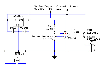
alright, so using my existing 7805 circuit, is this correct??
Also, adding this stuff to the existing 7805 circuit won't affect the connectors I have there to power the displays will it?
bigjohnny 
Copper - Posts: 293
Copper spacespace
Joined: September 23, 2008
Location: Ontario, Canada
Posted: July 12, 2009 at 4:00 PM / IP Logged  
forgot the freakin image
temperature displays - Page 7 -- posted image.
i am an idiot 
Platinum - Posts: 13,670
Platinum spaceThis member consistently provides reliable informationspace
Joined: September 21, 2006
Location: Louisiana, United States
Posted: July 12, 2009 at 4:33 PM / IP Logged  
All looks well.  The extra load on the 7805 will be minimal.  J1 and J2 are to power the displays? 
bigjohnny 
Copper - Posts: 293
Copper spacespace
Joined: September 23, 2008
Location: Ontario, Canada
Posted: July 12, 2009 at 5:00 PM / IP Logged  
yeah, they are just connectors, I'm going to have to add two more to power the amp and volt meters, but Im waiting for my VB1212S-1W Isolators to arrive.
If only I had the stuff to make a PCB, that would rock.
I'll get the stuff to build this on wed or thurs and get it together.
bigjohnny 
Copper - Posts: 293
Copper spacespace
Joined: September 23, 2008
Location: Ontario, Canada
Posted: July 17, 2009 at 7:23 AM / IP Logged  
I picked up the parts but I have the transistor on order as well as the 100 ohm pot. a trim pot will work right?
I just have to find a perf board now, and get some connectors.
is there anywhere I can have a single PCB designed for this circuit? I don't want to have to buy a massive quantity of PCBs just so it can be made. I don't have thesupplies or knowledge to design PCBs.
i am an idiot 
Platinum - Posts: 13,670
Platinum spaceThis member consistently provides reliable informationspace
Joined: September 21, 2006
Location: Louisiana, United States
Posted: July 17, 2009 at 2:27 PM / IP Logged  
The circuit is really small enough to assemble on a project board.  This one would be way more than enough area to do what you need.  .radioshack.com/ 2102845
Let's Go Brandon Brown. Congratulations on your first Xfinity Series Win. LGBFJB
bigjohnny 
Copper - Posts: 293
Copper spacespace
Joined: September 23, 2008
Location: Ontario, Canada
Posted: July 17, 2009 at 5:03 PM / IP Logged  
I was actually looking at that. In the past I've used perf boards with single holes. I can see how that might be easier, but isn't it hard to place components on a board that has a "pattern" like that?
What would be the best way to connect the components, wires? again, with the single hole boards, I've usually just bent the leads to connect with each other. I haven't built anything big before, so that's always worked out ok, but I would like to know how others who assemble circuits go about the connections/pathways.
i am an idiot 
Platinum - Posts: 13,670
Platinum spaceThis member consistently provides reliable informationspace
Joined: September 21, 2006
Location: Louisiana, United States
Posted: July 17, 2009 at 5:47 PM / IP Logged  
The 2 strips in the center of the board are used as power and ground.  Straddle the Chip over those strips.   The chip will insert into the holes directly outside of the strips, this will leave you 2 available connections for each pin on the chip.   If you have an old IDE ribbon cable for a computer hard drive laying around, a strand of that will make a great jumper wire.  The ribbon cable will work great for your project.  If you were doing something that requres more current, you will need larger wire.
Let's Go Brandon Brown. Congratulations on your first Xfinity Series Win. LGBFJB
KPierson 
Platinum - Posts: 3,527
Platinum spaceThis member consistently provides reliable informationspace
Joined: April 14, 2005
Location: Ohio, United States
Posted: July 17, 2009 at 7:13 PM / IP Logged  

Check out www.freepcb.com and www.barebonespcb.com

FreePCB is a free circuit board layout tool and barebonespcb is the best place I have found to buy custom "prototype" boards.  Once you lay out a small circuit this way you'll never touch another perf board.

On the perf boards, though, I used to actually solder the squares together (I would only use boards with square pads, the round pad boards always seemed to give me problems) to make traces.  If I had to jump a trace I would use a small jumper wire.  There are a million ways to do them, you just need to make sure they are laid out in a manner that allows easy trouble shooting.

Kevin Pierson
bigjohnny 
Copper - Posts: 293
Copper spacespace
Joined: September 23, 2008
Location: Ontario, Canada
Posted: July 17, 2009 at 10:28 PM / IP Logged  
thanks for the advice guys, ribbon cable is perfect, and I'm gonna def. check out the program/site.
it's the layout for troubleshooting that gets me lol, I've only made simple circuits before, not that this is complicated but there are going to be more connections than I'm used to....sometimes gets a little confusing following a diagram.
I also got my isolators today, turns out they are 12v (I don't know why this just clicked in now tbh, I must be stupid or something) so I'm going to have to put them on the 12v side and step the voltage down AFTER the isolators, which means actually building another 12 v - 5v regulator circuit. I may just reclaim my existing one and use it for this.
The other isolator will be for my voltage meter, and will isolate the voltage being measured. that way it will all work to the specs of the meters.
It says they can't measure the same source either, which means I would need another isolator(vb1212s-2w, dual output) but the diagrams provided by the company show both meters measuring the same source when isolated with the dc-dc isolators.
I'll get some scans in a bit.
Page of 9

  Printable version Printable version Post ReplyPost New Topic
You cannot post new topics in this forum
You cannot reply to topics in this forum
You cannot delete your posts in this forum
You cannot edit your posts in this forum
You cannot create polls in this forum
You cannot vote in polls in this forum

  •  
Search the12volt.com
Follow the12volt.com Follow the12volt.com on Facebook
Thursday, May 2, 2024 • Copyright © 1999-2024 the12volt.com, All Rights Reserved Privacy Policy & Use of Cookies
Disclaimer: *All information on this site ( the12volt.com ) is provided "as is" without any warranty of any kind, either expressed or implied, including but not limited to fitness for a particular use. Any user assumes the entire risk as to the accuracy and use of this information. Please verify all wire colors and diagrams before applying any information.

Secured by Sectigo
the12volt.com spacer
Support the12volt.com
Top
the12volt.com spacer