the12volt.com spacer
icon

temperature displays


Post ReplyPost New Topic
< Prev Topic Next Topic >
bigjohnny 
Copper - Posts: 293
Copper spacespace
Joined: September 23, 2008
Location: Ontario, Canada
Posted: July 12, 2009 at 8:13 AM / IP Logged  
my existing regulator circuit has only pos/neg output.... I would need to tap into the "in" pin on that circuit connecting it to Q1?
you know, it's probably just easier if I buy another 7805 and just build this as it is.... no need to make it more complicated.
any suggestions on a relay? or will any relay rated for my purposes do the job?
i am an idiot 
Platinum - Posts: 13,670
Platinum spaceThis member consistently provides reliable informationspace
Joined: September 21, 2006
Location: Louisiana, United States
Posted: July 12, 2009 at 8:21 AM / IP Logged  

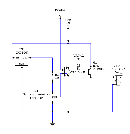
I was assuming you were going to use a standard automotive relay.  If you are using a smaller relay, we may be able to use a smaller transistor.  As the diagram sits, you can use pretty much any relay with a 12 volt coil.  If you are using a smaller relay, let me know the resistance of the coil and we may be able to use a smaller transistor as well. 

You do not have to connect to the input pin of the regulator.  You can connect it to the source that is feeding the input pin of the regulators.  

bigjohnny 
Copper - Posts: 293
Copper spacespace
Joined: September 23, 2008
Location: Ontario, Canada
Posted: July 12, 2009 at 8:53 AM / IP Logged  
I was going to use any relay I could find that would work basically... maybe not standard automotive since I was gonna take a look around my dads garage.....he's got tons of stuff like that.
a heater would tend to draw a lot of current, so I just need a relay that can handle what the heater would draw, if an automotive relay can do it, I'll buy one. I'm not worried about using smaller components, nothing wrong with overbuilding ;)
now about that last comment..... what?!?! if it's easier just to buy a second 7805 I'll go that route, I'm just not sure how to squeeze my existing regulator circuit into this one.
i am an idiot 
Platinum - Posts: 13,670
Platinum spaceThis member consistently provides reliable informationspace
Joined: September 21, 2006
Location: Louisiana, United States
Posted: July 12, 2009 at 9:18 AM / IP Logged  
What are you using as a 12 volt source?  
bigjohnny 
Copper - Posts: 293
Copper spacespace
Joined: September 23, 2008
Location: Ontario, Canada
Posted: July 12, 2009 at 9:34 AM / IP Logged  
for the heater?? the battery most likely, The heater I was looking at I believe needs to be wired right to the battery.
power source for the circuitry components would be any 12v source I can fin in the dash, possibly ignition so the displays/heater will be active with KOEO.
just backing up a bit here, you said depending on weather its for heat or cool I should reverse the polarity on the op-amp pins 2 and 3.
first of all how would that make difference, what would it do differently, and secondly, I could just wire a switch into that to make it switchable between heat and cool, and go so far as to add some fans for cooling functions?
sorry about all the questions, im sure you have better things to do, I'm just trying to nail down all the specifics so I can get this assembled without issue.
i am an idiot 
Platinum - Posts: 13,670
Platinum spaceThis member consistently provides reliable informationspace
Joined: September 21, 2006
Location: Louisiana, United States
Posted: July 12, 2009 at 9:52 AM / IP Logged  
The way the picture is, anytime pin 2 goes lower than pin 3 the relay will energize.  From what I am gathering, you need opposite of this.
bigjohnny 
Copper - Posts: 293
Copper spacespace
Joined: September 23, 2008
Location: Ontario, Canada
Posted: July 12, 2009 at 10:06 AM / IP Logged  
so I should have the probe connected to pin 3, and the pot connected to pin 2?
i am an idiot 
Platinum - Posts: 13,670
Platinum spaceThis member consistently provides reliable informationspace
Joined: September 21, 2006
Location: Louisiana, United States
Posted: July 12, 2009 at 10:26 AM / IP Logged  
correct
bigjohnny 
Copper - Posts: 293
Copper spacespace
Joined: September 23, 2008
Location: Ontario, Canada
Posted: July 12, 2009 at 10:40 AM / IP Logged  
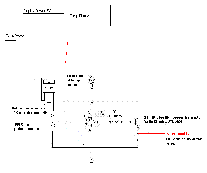
I'm still working on the labels, and getting the hang of this program (Circuit Maker 2000) but this is basically the circuit?
temperature displays - Page 6 -- posted image.
i am an idiot 
Platinum - Posts: 13,670
Platinum spaceThis member consistently provides reliable informationspace
Joined: September 21, 2006
Location: Louisiana, United States
Posted: July 12, 2009 at 1:53 PM / IP Logged  
i am an idiot wrote:

I changed the value of the resistor that connects to the 7805.  With the 1K resistor the control would be from 0 to (.)49 volts.  With the 10K resistor you will have much better control.

temperature displays - Page 6 -- posted image.

Page of 9

  Printable version Printable version Post ReplyPost New Topic
You cannot post new topics in this forum
You cannot reply to topics in this forum
You cannot delete your posts in this forum
You cannot edit your posts in this forum
You cannot create polls in this forum
You cannot vote in polls in this forum

  •  
Search the12volt.com
Follow the12volt.com Follow the12volt.com on Facebook
Wednesday, May 8, 2024 • Copyright © 1999-2024 the12volt.com, All Rights Reserved Privacy Policy & Use of Cookies
Disclaimer: *All information on this site ( the12volt.com ) is provided "as is" without any warranty of any kind, either expressed or implied, including but not limited to fitness for a particular use. Any user assumes the entire risk as to the accuracy and use of this information. Please verify all wire colors and diagrams before applying any information.

Secured by Sectigo
the12volt.com spacer
Support the12volt.com
Top
the12volt.com spacer