the12volt.com spacer
icon

temperature displays


Post ReplyPost New Topic
< Prev Topic Next Topic >
bigjohnny 
Copper - Posts: 293
Copper spacespace
Joined: September 23, 2008
Location: Ontario, Canada
Posted: July 10, 2009 at 11:33 AM / IP Logged  

I have a 7805 circuit built already to power the displays. it also has the caps to smooth out spikes. Done as provided by the fine people here. :)

So I already have that I can tap into, It will be powering both temp displays, and could probably power this new circuit I need to build.

I could not for the life of me ever figure out what parts I need to do what I want here, but if you guys know the parts needed I can buy'em and build it.

this is really low voltage too, 0.030v for 0*C, and around 0.017v for 24*c

bigjohnny 
Copper - Posts: 293
Copper spacespace
Joined: September 23, 2008
Location: Ontario, Canada
Posted: July 10, 2009 at 7:57 PM / IP Logged  
sort of off topic, but are there any decent programs to design circuit boards/PCBs, and/or make wiring diagrams easily?
I think I used something called smartdraw in the past when I was dabbling with electronics. anything better/more useful around?
bigjohnny 
Copper - Posts: 293
Copper spacespace
Joined: September 23, 2008
Location: Ontario, Canada
Posted: July 11, 2009 at 10:07 AM / IP Logged  
no word on resistor/transistor values yet? I would like to go and pickup the parts today so I can make this as I'm pretty well finished the dash beze, to mount the stuff, I wanna get it all back in my car.
i am an idiot 
Platinum - Posts: 13,670
Platinum spaceThis member consistently provides reliable informationspace
Joined: September 21, 2006
Location: Louisiana, United States
Posted: July 11, 2009 at 9:04 PM / IP Logged  

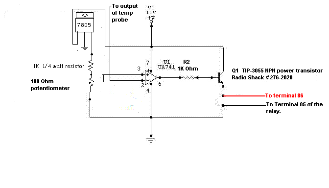
When the voltage on pin 2 goes below the voltage on pin 3, the relay will energize.  I did not go back and see how your probe reacts to temp, nor did I go back and see if it is to trigger a fan at a high temp or a heater at low temp.  If it is backwards this way, simply reverse pins 2 and 3 of the diagram. 

temperature displays - Page 5 -- posted image.

bigjohnny 
Copper - Posts: 293
Copper spacespace
Joined: September 23, 2008
Location: Ontario, Canada
Posted: July 12, 2009 at 7:10 AM / IP Logged  
Thanks, It will trigger a heater at low temp. The probe reacts like a thermistor...temp goes up, resistance goes up, voltage goes down.
it's all very tiny voltage, 24*C shows a voltage of 0.017v
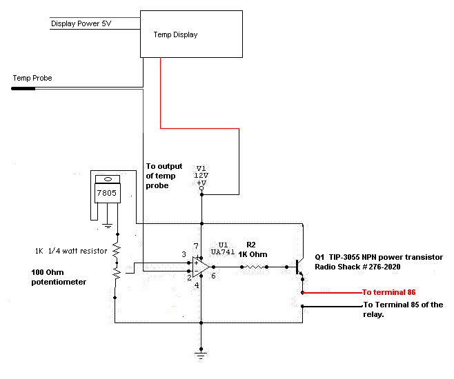
anyway let me make sure I've got this straight V1 is what?? is that what connects back to the circuit board where the probe red wire was, and "output of temp probe" is where the red wire from the probe connects?
So is this what I would be doing?
temperature displays - Page 5 -- posted image.
i am an idiot 
Platinum - Posts: 13,670
Platinum spaceThis member consistently provides reliable informationspace
Joined: September 21, 2006
Location: Louisiana, United States
Posted: July 12, 2009 at 7:27 AM / IP Logged  

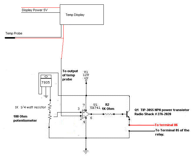
The non positive wire of the probe should be already connected to ground inside the Temp Display.    Check that for me.  V1 is 12 volts to supply power to the circuit and power the relay.  Do not run 12 volts back into the display.  If I remember correctly, that is what this thread was started by. 

You have to leave the probe connected to the display.  Simply attach the wire from this circuit along with the probe wire.

temperature displays - Page 5 -- posted image.

bigjohnny 
Copper - Posts: 293
Copper spacespace
Joined: September 23, 2008
Location: Ontario, Canada
Posted: July 12, 2009 at 7:36 AM / IP Logged  
I'll double check and get back about the probe grounding in about 20 mins, but I don't think it is(I could be wrong) because in order to get an actual reading of probe voltage I had to measure the probe red against the displays ground.
When I tested both probe wires, the voltage didn't do anything..... the value is posted on page one I think, but it did nothing as temp changed.
now that 7805, it produces 5v? and does what?
I've already built a 7805 circuit to power the two displays, and my volt/amp meters, could I use that existing circuit to power this instead of the 7805 in the diagram, or is that needed for this circuit specifically?
bigjohnny 
Copper - Posts: 293
Copper spacespace
Joined: September 23, 2008
Location: Ontario, Canada
Posted: July 12, 2009 at 7:50 AM / IP Logged  
I am unable to determine if the probe ground is connected directly to the display ground, but here is a pic of the circuit board, as mentioned above, I don't think it is directly connected.
temperature displays - Page 5 -- posted image.
i am an idiot 
Platinum - Posts: 13,670
Platinum spaceThis member consistently provides reliable informationspace
Joined: September 21, 2006
Location: Louisiana, United States
Posted: July 12, 2009 at 7:51 AM / IP Logged  

You can use your present regulators.  There is minimal current draw from this circuit. 

No need to check the probe.  If the voltage is changing when referenced to actual ground.  This is what we need.

i am an idiot 
Platinum - Posts: 13,670
Platinum spaceThis member consistently provides reliable informationspace
Joined: September 21, 2006
Location: Louisiana, United States
Posted: July 12, 2009 at 8:07 AM / IP Logged  

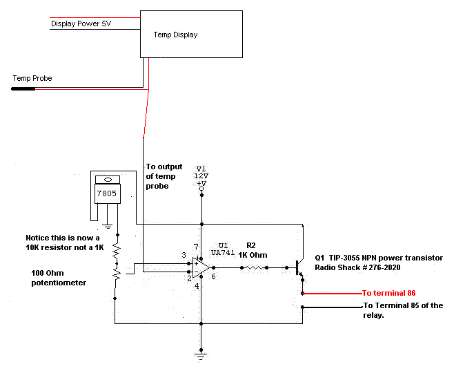
I changed the value of the resistor that connects to the 7805.  With the 1K resistor the control would be from 0 to (.)49 volts.  With the 10K resistor you will have much better control.

temperature displays - Page 5 -- posted image.

Page of 9

  Printable version Printable version Post ReplyPost New Topic
You cannot post new topics in this forum
You cannot reply to topics in this forum
You cannot delete your posts in this forum
You cannot edit your posts in this forum
You cannot create polls in this forum
You cannot vote in polls in this forum

  •  
Search the12volt.com
Follow the12volt.com Follow the12volt.com on Facebook
Wednesday, May 8, 2024 • Copyright © 1999-2024 the12volt.com, All Rights Reserved Privacy Policy & Use of Cookies
Disclaimer: *All information on this site ( the12volt.com ) is provided "as is" without any warranty of any kind, either expressed or implied, including but not limited to fitness for a particular use. Any user assumes the entire risk as to the accuracy and use of this information. Please verify all wire colors and diagrams before applying any information.

Secured by Sectigo
the12volt.com spacer
Support the12volt.com
Top
the12volt.com spacer