the12volt.com spacer
icon

temperature displays


Post ReplyPost New Topic
< Prev Topic Next Topic >
i am an idiot 
Platinum - Posts: 13,670
Platinum spaceThis member consistently provides reliable informationspace
Joined: September 21, 2006
Location: Louisiana, United States
Posted: June 10, 2009 at 7:43 PM / IP Logged  

I was going to find you a part number for the transistor, but then I noticed the resistor above and to the left a bit.  Then I noticed the trace from the resistor to the microprocessor has heated up.  The microprocessor is probably toast.

KPierson 
Platinum - Posts: 3,527
Platinum spaceThis member consistently provides reliable informationspace
Joined: April 14, 2005
Location: Ohio, United States
Posted: June 10, 2009 at 8:51 PM / IP Logged  

If you look at all the "fingers" under the RHOS type that is most likely where the screen makes a connection with the board.  They use a "zebra" strip thats basically a conductive cushion to make the connection between screens and boards.  If you don't look at the little strip closely you would never guess that it is conductive.  This is also why if you don't put enough pressure on it the actual display doesn't work.  The only thing is is that I never saw a zebra strip in any of the pictures!

How are you burning these things up?

Kevin Pierson
i am an idiot 
Platinum - Posts: 13,670
Platinum spaceThis member consistently provides reliable informationspace
Joined: September 21, 2006
Location: Louisiana, United States
Posted: June 10, 2009 at 8:59 PM / IP Logged  
Bottom right of the second picture he posted.  It is black in color instead of the conventional grey.
KPierson 
Platinum - Posts: 3,527
Platinum spaceThis member consistently provides reliable informationspace
Joined: April 14, 2005
Location: Ohio, United States
Posted: June 10, 2009 at 9:08 PM / IP Logged  

i am an idiot wrote:
Bottom right of the second picture he posted.  It is black in color instead of the conventional grey.

Wow, good eye.  I didn't scroll over and it was completely cut off my screen!

I think you can also see it in the first picture too, it's just really small and hard to make out.

Kevin Pierson
bigjohnny 
Copper - Posts: 293
Copper spacespace
Joined: September 23, 2008
Location: Ontario, Canada
Posted: June 12, 2009 at 8:50 PM / IP Logged  
I wondered if that was how it was done, thats neat I've never seen that before.
How do I keep burning them out? I had them wired backwards, they are polarity sensitive... I won't make that mistake again.
seeing the unit now, how can I determine if this can control a relay at a certain temp? how would I measure the voltage from the thermistor?
bigjohnny 
Copper - Posts: 293
Copper spacespace
Joined: September 23, 2008
Location: Ontario, Canada
Posted: July 09, 2009 at 9:15 PM / IP Logged  
Alrighty, so coming back to this now, I've got my new meters, I've measured the voltage from the theristor across the thermistor positive, and the main power negative, this seemed to have a more definitive effect over the last measurement.
I wrapped up the probe in an ice pack and observed the voltage going up as temp went down.
At 0C the voltage was 0.032v - 0.035 (measured using my meters 2v DC setting)
so what kind of op amp would I need to trigger a relay when the voltage hits 0.030?
KPierson 
Platinum - Posts: 3,527
Platinum spaceThis member consistently provides reliable informationspace
Joined: April 14, 2005
Location: Ohio, United States
Posted: July 10, 2009 at 6:09 AM / IP Logged  

tid=105885&KW=low+fuel

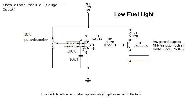
There is the op amp circuit that I am an idiot posted.

For such a low voltage you may need to modify the 10K pot on pin 3 of the op amp to include a 2nd resistor in series with the pot (creating a voltage divider and allowing you to focus the pot on a smaller voltage range).

I would also recomend getting a pot with as many turns as possible (>20).  That will allow you to dial in the voltage with more precision.

Kevin Pierson
bigjohnny 
Copper - Posts: 293
Copper spacespace
Joined: September 23, 2008
Location: Ontario, Canada
Posted: July 10, 2009 at 6:51 AM / IP Logged  
hey thanks, I could not find that for the life of me.
as I understand that the "gauge input" would be the positive lead from the probe, and the "LED" leads would be the ones that trigger the relay?
what value should I use for the 2nd resistor?
it would be like this ? (stuff added is in red)
I should also mention that I'm not very well versed with wiring diagrams, I understand it to a point, but some of the symbolbs i'm unsure of, or certain connections. like the 12V +V?? The probe would be connected to the slosh module input and the 12V +V would be 12V positive power?
temperature displays - Page 4 -- posted image.
i am an idiot 
Platinum - Posts: 13,670
Platinum spaceThis member consistently provides reliable informationspace
Joined: September 21, 2006
Location: Louisiana, United States
Posted: July 10, 2009 at 7:31 AM / IP Logged  
R1 is to limit the current to the LED.  If driving a relay, it needs to be eliminated.  You will need a different transistor.  With the voltage you need it to turn on at, it is going to be really hard to set with the 100K pot.  We will have to add a resistor at the top ot the potentiometer and maybe use a 470 ohm potentiometer.  This will eliminate the extra resistor you added and give you much more control.  I will get you a resistor value tonight.  I have a diagram that uses a 7805 regulator to give a more stable control.  I will modify it tonight also.
KPierson 
Platinum - Posts: 3,527
Platinum spaceThis member consistently provides reliable informationspace
Joined: April 14, 2005
Location: Ohio, United States
Posted: July 10, 2009 at 8:30 AM / IP Logged  

Why would the transistor need to be replaced?  I'm not familiar with the 2n2222 but I always thought itw as a fairly decent general purpose transistor (it seems to be the most common transistor used on internet diagrams).  If the 2n2222 doesn't work I know a 2n3904 will work.

The base resistor, R2, will have to be dropped quite a bit, as well, probably down to 470 ohms if I had to guess.

Kevin Pierson
Page of 9

  Printable version Printable version Post ReplyPost New Topic
You cannot post new topics in this forum
You cannot reply to topics in this forum
You cannot delete your posts in this forum
You cannot edit your posts in this forum
You cannot create polls in this forum
You cannot vote in polls in this forum

  •  
Search the12volt.com
Follow the12volt.com Follow the12volt.com on Facebook
Wednesday, May 8, 2024 • Copyright © 1999-2024 the12volt.com, All Rights Reserved Privacy Policy & Use of Cookies
Disclaimer: *All information on this site ( the12volt.com ) is provided "as is" without any warranty of any kind, either expressed or implied, including but not limited to fitness for a particular use. Any user assumes the entire risk as to the accuracy and use of this information. Please verify all wire colors and diagrams before applying any information.

Secured by Sectigo
the12volt.com spacer
Support the12volt.com
Top
the12volt.com spacer