the12volt.com spacer
icon

how to test relay from jbl amplifier?


Post ReplyPost New Topic
< Prev Topic Next Topic >
craig155 
Member - Posts: 37
Member spacespace
Joined: April 19, 2009
Location: United Kingdom
Posted: April 23, 2009 at 5:49 PM / IP Logged  
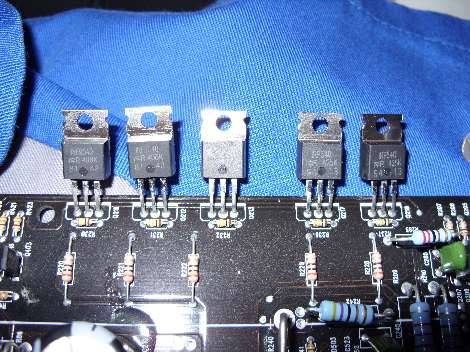
how to test relay from jbl amplifier? - Page 2 -- posted image.
craig155 
Member - Posts: 37
Member spacespace
Joined: April 19, 2009
Location: United Kingdom
Posted: April 23, 2009 at 5:49 PM / IP Logged  
Hope these are readible
i am an idiot 
Platinum - Posts: 13,714
Platinum spaceThis member consistently provides reliable informationspace
Joined: September 21, 2006
Location: Louisiana, United States
Posted: April 23, 2009 at 8:41 PM / IP Logged  

Yes they are legible.  The ones labeled IRF-540 are the outputs.  Do you have a digital meter?   Do you know where the diode test function is located on the meter? 

how to test relay from jbl amplifier? - Page 2 -- posted image.is the symbol for a diode.  The diode test function should have a similar symbol.

craig155 
Member - Posts: 37
Member spacespace
Joined: April 19, 2009
Location: United Kingdom
Posted: April 24, 2009 at 7:15 PM / IP Logged  
yes, i have seen a similar post that you have helped with, i will post the readings shortly.
i am an idiot 
Platinum - Posts: 13,714
Platinum spaceThis member consistently provides reliable informationspace
Joined: September 21, 2006
Location: Louisiana, United States
Posted: April 24, 2009 at 9:04 PM / IP Logged  
Do not pull the transistors out of the board. Chances are there is only one on each side that is actually shorted. You will need to replace all associated with the one that shorted. They all went through the same abuse, the ones that did not fail are more than likely weak and will not hold up. After you locate the shorted one or 2, you can remove them and see if the amp works. Do not play it loud or long, we just need to see if that is the only damage.
To check them, one meter lead on the metal case of the transistor, the other lead to the right leg of the transistor. If it reads near a dead short, one of the ones in that bank is shorted. To find the shorted one, move the lead from the right leg to the left leg. Check all of them and notice the readings. One will read lower than the rest. That one is shorted. Remove it and check the ones on the other side. Remove the shorted one there too. Make sure there are no solder bridges on the ones you removed. It really needs to be put back in the heat sink and all transistors clamped down when testing it. Remove all fuses on the amp and place a single 10 amp fuse for testing.
craig155 
Member - Posts: 37
Member spacespace
Joined: April 19, 2009
Location: United Kingdom
Posted: April 25, 2009 at 9:53 AM / IP Logged  

With the board facing up and the phonos to the right, the readings are 493/514  491/513 these are the top ones.

the bottom two are 483/1018  489/1029, do these figure make sense?

Thanks for the help by the way

craig155 
Member - Posts: 37
Member spacespace
Joined: April 19, 2009
Location: United Kingdom
Posted: April 25, 2009 at 10:14 AM / IP Logged  

If i have 1 lead on the left leg and the other on the right leg i get a buzzer sound from the multimeter, this happens on the 2 top transistors and accross the resistors? at their base.

Are these the defective ones?

i am an idiot 
Platinum - Posts: 13,714
Platinum spaceThis member consistently provides reliable informationspace
Joined: September 21, 2006
Location: Louisiana, United States
Posted: April 25, 2009 at 9:51 PM / IP Logged  
How many 540s are there on each side of the amp?
craig155 
Member - Posts: 37
Member spacespace
Joined: April 19, 2009
Location: United Kingdom
Posted: April 26, 2009 at 7:07 AM / IP Logged  
There are 2 540's on each side of the board and 3 9540's on each side.
i am an idiot 
Platinum - Posts: 13,714
Platinum spaceThis member consistently provides reliable informationspace
Joined: September 21, 2006
Location: Louisiana, United States
Posted: April 26, 2009 at 7:50 AM / IP Logged  

Check each of the 540s and 9540s as follows.  Red meter lead on metal tab of transistor, black lead on the right leg.  Let me know how many of what type are reading near 0.000 on the meter.

When it was buzzing at you the way you tested it earlier, what was the meter reading at that time?

Page of 6

  Printable version Printable version Post ReplyPost New Topic
You cannot post new topics in this forum
You cannot reply to topics in this forum
You cannot delete your posts in this forum
You cannot edit your posts in this forum
You cannot create polls in this forum
You cannot vote in polls in this forum

  •  
Search the12volt.com
Follow the12volt.com Follow the12volt.com on Facebook
Thursday, July 3, 2025 • Copyright © 1999-2025 the12volt.com, All Rights Reserved Privacy Policy & Use of Cookies
Disclaimer: *All information on this site ( the12volt.com ) is provided "as is" without any warranty of any kind, either expressed or implied, including but not limited to fitness for a particular use. Any user assumes the entire risk as to the accuracy and use of this information. Please verify all wire colors and diagrams before applying any information.

Secured by Sectigo
the12volt.com spacer
Support the12volt.com
Top
the12volt.com spacer