the12volt.com spacer
icon

how to test relay from jbl amplifier?


Post ReplyPost New Topic
< Prev Topic Next Topic >
craig155 
Member - Posts: 37
Member spacespace
Joined: April 19, 2009
Location: United Kingdom
Posted: April 26, 2009 at 4:53 PM / IP Logged  

None are reading near zero, the 540s are showing 1222.

When it was buzzing, they were showing 030.

i am an idiot 
Platinum - Posts: 13,714
Platinum spaceThis member consistently provides reliable informationspace
Joined: September 21, 2006
Location: Louisiana, United States
Posted: April 26, 2009 at 5:29 PM / IP Logged  
It is rare for them to short from leg 1 to leg 3.  But it does happen.  You will have to remove those 2 to test them further.  To remove them, heat the joints up and add extra solder to all 3 joints on each part.  Now lay your iron across all 3 joints and the transistor should fall out of the board.  If it does not fall out, use some small pliers and gently pull the part out of the board.  The pliers are only so you do not burn your fingers.  Do not force them out with the pliers.  Check them again from left leg to right leg.  Let me know what you find out.
craig155 
Member - Posts: 37
Member spacespace
Joined: April 19, 2009
Location: United Kingdom
Posted: April 26, 2009 at 5:56 PM / IP Logged  

 removed the 2 540s and checked leg 1 & 3 no buzzer, meter stayed showing 1.

I also removed the 2 resistors and they did not buzz either.

The funny thing is that i checked the joints that the transistors and resistors came out of  and they made the multimeter buzz.

Any idas?

i am an idiot 
Platinum - Posts: 13,714
Platinum spaceThis member consistently provides reliable informationspace
Joined: September 21, 2006
Location: Louisiana, United States
Posted: April 26, 2009 at 6:12 PM / IP Logged  

Check the transistors on the other side of the board the same way.   

craig155 
Member - Posts: 37
Member spacespace
Joined: April 19, 2009
Location: United Kingdom
Posted: April 26, 2009 at 6:17 PM / IP Logged  
same readings
i am an idiot 
Platinum - Posts: 13,714
Platinum spaceThis member consistently provides reliable informationspace
Joined: September 21, 2006
Location: Louisiana, United States
Posted: April 26, 2009 at 7:19 PM / IP Logged  
Are you sure that they are IRF-540 or IRF-9540?  The rectifier diodes will read like that when in circuit.  If they are 540 or 9540, remove them and test out of circuit.
craig155 
Member - Posts: 37
Member spacespace
Joined: April 19, 2009
Location: United Kingdom
Posted: April 27, 2009 at 12:07 PM / IP Logged  

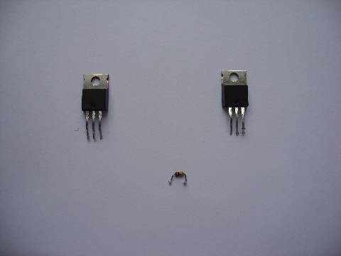
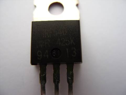
They are definately IRF 540 and IRF 9540.

With the black lead on the metal body if you then touch the right leg you get a reading,if you then touch the left leg the meter stays showing 1.

If you then touch the right leg again the buzzer sounds.

This happens on both transistors.

If you leave them for a couple of minutes the same as above happens.

craig155 
Member - Posts: 37
Member spacespace
Joined: April 19, 2009
Location: United Kingdom
Posted: April 27, 2009 at 12:16 PM / IP Logged  
how to test relay from jbl amplifier? - Page 3 -- posted image.
craig155 
Member - Posts: 37
Member spacespace
Joined: April 19, 2009
Location: United Kingdom
Posted: April 27, 2009 at 12:17 PM / IP Logged  
how to test relay from jbl amplifier? - Page 3 -- posted image.
i am an idiot 
Platinum - Posts: 13,714
Platinum spaceThis member consistently provides reliable informationspace
Joined: September 21, 2006
Location: Louisiana, United States
Posted: April 27, 2009 at 3:24 PM / IP Logged  
That is how they are supposed to work.  Once you touch the lead to the left leg, you turn the transistor on.  It will remain on until you turn it off by holding the red lead to the case and touching the black lead to the left leg.  You stated that from left leg to right leg it read .030, what happened with that?   Chack the board from left hole to right hole.  I can tell nothing by learning of a buzz from your meter.  I need to know numbers from here on out. 
Page of 6

  Printable version Printable version Post ReplyPost New Topic
You cannot post new topics in this forum
You cannot reply to topics in this forum
You cannot delete your posts in this forum
You cannot edit your posts in this forum
You cannot create polls in this forum
You cannot vote in polls in this forum

  •  
Search the12volt.com
Follow the12volt.com Follow the12volt.com on Facebook
Friday, July 4, 2025 • Copyright © 1999-2025 the12volt.com, All Rights Reserved Privacy Policy & Use of Cookies
Disclaimer: *All information on this site ( the12volt.com ) is provided "as is" without any warranty of any kind, either expressed or implied, including but not limited to fitness for a particular use. Any user assumes the entire risk as to the accuracy and use of this information. Please verify all wire colors and diagrams before applying any information.

Secured by Sectigo
the12volt.com spacer
Support the12volt.com
Top
the12volt.com spacer