the12volt.com spacer
icon

viper 5901 into a 2005 nissan 350z


Post ReplyPost New Topic
< Prev Topic Next Topic >
zenica 
Copper - Posts: 116
Copper spaceThis member has made a donation to the12volt.com. Click here for more info.spacespace
Joined: August 08, 2005
Location: United States
Posted: April 24, 2009 at 10:20 PM / IP Logged  
I downloaded that BL PDF file, I see what you mean, it indicates the rear hatch is BCM 30 but I didn't see where it indicated what that terminal will rest on.
I checked all of the other leads, some are 12v, some are ground already and others were nothing but only one reacts at all when that hatch button is pressed and it is the one that rests at 5v going to ground when the button is pressed.
mikvot 
Gold - Posts: 1,043
Gold spaceThis member has made a donation to the12volt.com. Click here for more info.spacespace
Joined: December 19, 2006
Location: Missouri, United States
Posted: April 24, 2009 at 10:27 PM / IP Logged  
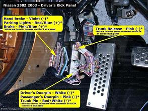
viper 5901 into a 2005 nissan 350z - Page 5 -- posted image.
zenica 
Copper - Posts: 116
Copper spaceThis member has made a donation to the12volt.com. Click here for more info.spacespace
Joined: August 08, 2005
Location: United States
Posted: April 24, 2009 at 10:34 PM / IP Logged  
Mikvot, Thanks for the illustration but it is too small to get a good look at what is being shown. I tried to enlarge the image but clarity was further reduced. It does say 2003, is that the same as in 2005? My BCM seems to sit in the car differently that in your picture.
zenica 
Copper - Posts: 116
Copper spaceThis member has made a donation to the12volt.com. Click here for more info.spacespace
Joined: August 08, 2005
Location: United States
Posted: April 24, 2009 at 11:45 PM / IP Logged  
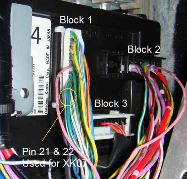
I must need sleep. I checked that wire that was previously 5v > ground when the hatch release was pressed, now it is not 5v. It is no volts. I give up checking online for BCM pinout diagrams since none seem to differentiate between the 3 plugs and one can spend all day chasings ones own tail trying to figure it out. Where in this image is the alleged hatch release wire? Also, do I need to wire in the dome light or is that handled by the unlock command though the unlock wires.
Sorry about the crappy pic quality but 50kb limit doesn't allow room for quality
viper 5901 into a 2005 nissan 350z - Page 5 -- posted image.
KPierson 
Platinum - Posts: 3,527
Platinum spaceThis member consistently provides reliable informationspace
Joined: April 14, 2005
Location: Ohio, United States
Posted: April 25, 2009 at 6:21 AM / IP Logged  

It's all in the manual, check again!

The "terminals and reference" page is 34 and it shows it rests at 5vdc and goes to ground when pushed.  You can also look at the diagram and see the "other" side (not bcm) is connected to ground, and therefore when the button is pushed it MUST go to ground.

To get the pinout of the BCM you need to check the pg.pdf file.  I'm not sure why they don't lay the BCM plugs out on that page, but they do in the pg.pdf file.  Check out page 83 of the pg.pdf file and it will show you the three plugs of the BCM.  Pin 30 should be right in the middle of the white 40 pin plug.  From your picture, it looks like the pink wire that is shown by your circles is the correcft wire.  You need to make sure the BCM hasn't "fallen asleep" as this may cause you to lose the voltage.

Finding the tach wire will require a bit of research in the EC.pdf file.  A little after page 100 you'll find the pinout for the entire ECU.  Go through it and find all 6 fuel injectors.  Pick a color that you think may be unique to the ECU and then check all the other pins to make sure it is unique.  That way, the fuel injector should be the only wire of that color at the ECU and it will make finding it much easier.  For example, I believe one of them is RED / black and there are three different RED / black wires at the ECU, so pick a different fuel injector wire to find. 

Kevin Pierson
Chris Luongo 
Platinum - Posts: 3,746
Platinum spaceThis member consistently provides reliable informationspace
Joined: May 21, 2002
Location: Massachusetts, United States
Posted: April 25, 2009 at 10:01 AM / IP Logged  
Ok, looking at the picture there....
Block 1 will have your CAN High, CAN Low, trunk release, and Security LED wires.
Block 2 (If memory serves) should have your individual left/right door trigger wires, the trunk trigger, and a domelight wire that'll catch both doors.
Block 3 should have the wires going to the doorlock motors inside the doors......nothing you need over there.
P.S. Those wires for the XK07 don't look right to me. They should be blue and pink, in one of the corners of the plug. And if you follow the wires a little further, they should be twisted together.
But again, just see if the XK07 programs or not when you get the install done. If XK07 has good ground, constant, and ignition, but doesn't program, you have the wrong data wires.
zenica 
Copper - Posts: 116
Copper spaceThis member has made a donation to the12volt.com. Click here for more info.spacespace
Joined: August 08, 2005
Location: United States
Posted: April 25, 2009 at 10:16 AM / IP Logged  
Thanks guys for the input.
After a good nights rest I am ready to try again.
I am going to download all of those PDF files, for now and future use. I wasn't aware or expecting the BCM could "sleep" or shut down...but given the volume of time I was working with it, I can see "sleep" happening.
The XK07 wires are obstructed by the wires you can see, the circle only indicates the general area I located them. They are the two corner ones, pink and blue is correct, thats what I found.
The door triggers, do I place a diode across them? I have read that you place a diode across them and grab the signal from just one. Is this because the alarm does not distinguish between an open drivers door vs an open passenger door?
zenica 
Copper - Posts: 116
Copper spaceThis member has made a donation to the12volt.com. Click here for more info.spacespace
Joined: August 08, 2005
Location: United States
Posted: April 25, 2009 at 10:46 AM / IP Logged  
ok, here is the deal.
That pink wire, pin 30. (I thought it was pin 31 because I made the error of counting the wires from the blank side rather than the HS or harness side)rests at 11.87v and goes to ground when the trunk release
is pressed. Is there a higher than expected voltage because the drivers door is open?
To be sure the BCM was awake I disconnected the battery for 5 mins
then reconnected it and used the master key to locl/unlock the doors through the drivers door key hole.
Why would it be 12v and not the 5v the manual is stating it ought to be?
EDIT
------------------------------------------------------------
What is the purpose of the 5901 H3/3 wire that is described as:
Connect this wire to the accessory wire that powers the climate control system.
Would not the climate control be turned on simply by the car starting?
Do I need this wire connected?
KPierson 
Platinum - Posts: 3,527
Platinum spaceThis member consistently provides reliable informationspace
Joined: April 14, 2005
Location: Ohio, United States
Posted: April 25, 2009 at 1:10 PM / IP Logged  

I personally wouldn't get too hung up on the actual voltage, it could be possible that the manual is wrong.  You have verified that the signal does go to ground when the button is pushed, so you can hook your (-) aux output up to it with no worries.

Block three is actually for stuff in the back of the car (rear wire, luggage light, hatch pin, etc), with the exception of the drivers side door pin (white wire).  The passengers door pin is pin 12 (pink).  The trunk pin is the red wire in block 3.

To catch the door pins you need to tap in to the drivers door and the passengers door and run those signals through dioes (stripe facing door pin wire) and then connect the non striped end of each diode to the door pin input of the alarm.  Alternatively, you can catch the dome light, but you'll have to disable the door opened warning so the alarm doesn't chirp when you lock the door and the dome light is still on. 

Kevin Pierson
zenica 
Copper - Posts: 116
Copper spaceThis member has made a donation to the12volt.com. Click here for more info.spacespace
Joined: August 08, 2005
Location: United States
Posted: April 25, 2009 at 1:28 PM / IP Logged  
KPierson wrote:

I personally wouldn't get too hung up on the actual voltage, it could be possible that the manual is wrong.  You have verified that the signal does go to ground when the button is pushed, so you can hook your (-) aux output up to it with no worries.

So it won't fry the brain? The book says it will only supply 200mA on that wire. So I would only introducing the 5901 wire into the OEM wire, not severing the OEM wire?
KPierson wrote:
Block three is actually for stuff in the back of the car (rear wire, luggage light, hatch pin, etc), with the exception of the drivers side door pin (white wire).  The passengers door pin is pin 12 (pink).  The trunk pin is the red wire in block 3.

To catch the door pins you need to tap in to the drivers door and the passengers door and run those signals through diodes (stripe facing door pin wire) and then connect the non striped end of each diode to the door pin input of the alarm.  Alternatively, you can catch the dome light, but you'll have to disable the door opened warning so the alarm doesn't chirp when you lock the door and the dome light is still on.

I want to be clear here, both drivers and passengers door trigger wires get diodes? Then I would take the none stripped end of each diode and connect them to the 5901 for a 3 way connection?
I put that part on hold while I obtain clarity and moved onto the ignition. I have the 5901 pink wire connected to the ignition      BLACK/ red wire at the ignition harness, I have the 5901 violet connected to the starter side of the WHITE/ red wire at the ignition harness and the 5901 green connected to the ignition side of the WHITE/ red wire at the ignition harness.
Do I need to do anything with the "starter 2" wire at the ignition harness? The 5901 states that pink with white and pink with black are used when an ignition switch isolation is necessary.
Page of 15

  Printable version Printable version Post ReplyPost New Topic
You cannot post new topics in this forum
You cannot reply to topics in this forum
You cannot delete your posts in this forum
You cannot edit your posts in this forum
You cannot create polls in this forum
You cannot vote in polls in this forum

  •  
Search the12volt.com
Follow the12volt.com Follow the12volt.com on Facebook
Monday, May 6, 2024 • Copyright © 1999-2024 the12volt.com, All Rights Reserved Privacy Policy & Use of Cookies
Disclaimer: *All information on this site ( the12volt.com ) is provided "as is" without any warranty of any kind, either expressed or implied, including but not limited to fitness for a particular use. Any user assumes the entire risk as to the accuracy and use of this information. Please verify all wire colors and diagrams before applying any information.

Secured by Sectigo
the12volt.com spacer
Support the12volt.com
Top
the12volt.com spacer