the12volt.com spacer
icon

viper 5901 into a 2005 nissan 350z


Post ReplyPost New Topic
< Prev Topic Next Topic >
KPierson 
Platinum - Posts: 3,527
Platinum spaceThis member consistently provides reliable informationspace
Joined: April 14, 2005
Location: Ohio, United States
Posted: April 25, 2009 at 1:44 PM / IP Logged  

The only OEM wire you will have to cut is the starter wire - this is for the starter kill.  Cutting the OEM security LED is optional, but not required.

The voltage on the wire doesn't matter, it's the amount of current you need to pay attention to.  This particular signal is just an input to the BCM so you can be certain the current draw is very, very low.

As far as the door pins, yes, you will need two diodes and both diodes will attach to the (-) door pin input wire of the alarm.

The 2nd starter wire should be hooked up to a 2nd starter output.  If you don't have a 2nd starter output there are options to create one - the "easiest" way is to just install an additional relay triggered off the starter output, or you can do it the "more correct" way which would be to keep the two starter wires completely isolated by installing two additional relays and triggering both of them off the starter output.

Kevin Pierson
zenica 
Copper - Posts: 116
Copper spaceThis member has made a donation to the12volt.com. Click here for more info.spacespace
Joined: August 08, 2005
Location: United States
Posted: April 25, 2009 at 2:03 PM / IP Logged  
In my case, I am cutting every wire. I have to do this because I am using heat shrink tubing and not tape but I get what your saying...
Is there a way for a DVOM to read/see mA so I can be sure the pink
wire at BCM pin 30 doesn't exceed 200mA.
The drivers and passengers wires are at the BCM, they are resting on ground? How should I test those to be sure I have the correct ones?
The 5901 has a 2nd starter wire relay built in, I just wasn't sure if
I needed to wire it. I will do that next.
I decided that since I have to drill a firewall hole for the hood pin and alarm horn, I may as well grab the tach from a coil pack like
you suggested. I isolated the wire I need from the 3 that are there.
EDIT
---------------------------------------------------------------------
Where the heck is the hood pin switch!?!
I don't see anything that looks like the traditional hood pin switch.
zenica 
Copper - Posts: 116
Copper spaceThis member has made a donation to the12volt.com. Click here for more info.spacespace
Joined: August 08, 2005
Location: United States
Posted: April 25, 2009 at 3:03 PM / IP Logged  
I got two silicone diodes, here are the specs:
Peak Inverse Voltage (PIV) 200V
Forward voltage drop at (if) 1.6V
Forward current (if) 1A
Max surge current (16ms) 30A
Reverse current at (PIV)10µA
Is this a suitable diode?
EDIT
-------------------------------------------------------------
Found the hood pin switch...
zenica 
Copper - Posts: 116
Copper spaceThis member has made a donation to the12volt.com. Click here for more info.spacespace
Joined: August 08, 2005
Location: United States
Posted: April 25, 2009 at 4:36 PM / IP Logged  
My hood pin switch has 2 wires, one white(ish) and one orange(ish).
Nothing is lt green like people say it should be...how should i test for the one I need, either the white or orange...
EDIT
---------------------------------------------------------------------
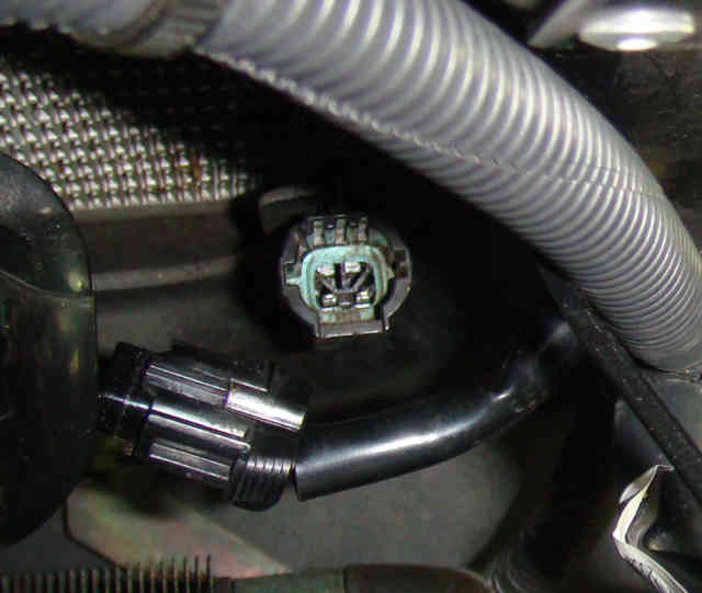
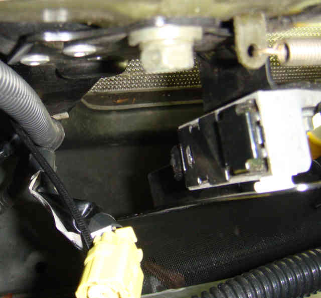
Which of these is the hood pin switch?
Neither one seems like a hood switch to me since neither one seems
to make any contact with anything let alone the ---uhm...hood.
viper 5901 into a 2005 nissan 350z - Page 6 -- posted image.
or
viper 5901 into a 2005 nissan 350z - Page 6 -- posted image.
t&t tech 
Platinum - Posts: 2,608
Platinum spacespace
Joined: October 05, 2008
Location: Trinidad and Tobago
Posted: April 25, 2009 at 5:05 PM / IP Logged  

set you meter for continuity test, put one probe to ground and the other to either of the wires on the hood switch, if you get continutiy right away, depress the switch if the continuity reading stops that's your wire, if it doesn't then the other wire will be the one,

commit your way to jehovah and he will act in your behalf. psalms 37:5
t&t tech 
Platinum - Posts: 2,608
Platinum spacespace
Joined: October 05, 2008
Location: Trinidad and Tobago
Posted: April 25, 2009 at 5:13 PM / IP Logged  

also you don't have to worry about how much draw the wire for the hatch release requires, once you have verified it goes to ground when the hatch is released then hook your RED / white aux aire directly to this wire, and try the pop, if it doesn't work you will need a relay to boost the alarm's signal,

also the second starter wire from the alarm i think is to be used via relay, i'm not sure let me know what the manual says about it, and post back so i can let you know how to wire the relay,

when the doors are opened the wires for the driver and passenger will be resting at ground, to test, set you meter to read 20v or so, and ground the black probe of the meter, and use the other probe to test the suspect wires, the passenger wire will go to twelve volts when the passenger door is closed and go to zero or ground when opened, same procedure for the driver's door.

commit your way to jehovah and he will act in your behalf. psalms 37:5
zenica 
Copper - Posts: 116
Copper spaceThis member has made a donation to the12volt.com. Click here for more info.spacespace
Joined: August 08, 2005
Location: United States
Posted: April 25, 2009 at 5:45 PM / IP Logged  
T&T,
Thanks...I had thought to try your suggestion about the hood pin switch
but the issue is this, there is nothing for me to depress or move or act upon in any way. Both of those ---what ever you want to call them---
that are in the pictures are static as far as I can see or feel. I have no idea how either one can be a hood switch since neither one comes in contact with the hood. Only one is even close enough to the hood latch to suggest it might be the hood switch but again, it makes no contact with anything that I can see or feel. The hood isn't even metal so it can't get grounded by the presence of the hood in the latch...so I am lost.
This is taken directly from the installation manual regarding the 2nd starter wire:
________________________________________________________________
H3/7 PINK/WHITE (+) IGNITION 2 FLEX RELAY OUTPUT
This wire is factory programmed as Ignition 2 and can be programmed as a 2nd accessory or as a 2nd starter.
________________________________________________________________
H3/8 PINK/BLACK 87a OF IGNITION 2 FLEX RELAY
This wire is used when an ignition switch isolation on the vehicle is necessary This is common on Toyota and Nissan's which require the use of Tech Tip document #1077.
(See Menu #3, Feature #8, for programming options)
________________________________________________________________
t&t tech 
Platinum - Posts: 2,608
Platinum spacespace
Joined: October 05, 2008
Location: Trinidad and Tobago
Posted: April 25, 2009 at 6:06 PM / IP Logged  

ok, well, why not mount an aftermarket pinswitch,   you can use the pink/white wire for the second starter, via a relay wired like this, single pole double throw relay just to be clear,

pin 30 to constant twelve

pin 85 to the pink/white wire from alarm

pin 86 to ignition

pin 87 to second starter wire

and you'll have to program the output to act as second starter

commit your way to jehovah and he will act in your behalf. psalms 37:5
zenica 
Copper - Posts: 116
Copper spaceThis member has made a donation to the12volt.com. Click here for more info.spacespace
Joined: August 08, 2005
Location: United States
Posted: April 25, 2009 at 6:24 PM / IP Logged  
The brain has that relay internal.
I should have elaborated or given more of what the installation manual has...here is the entire section for the Heavy Gauge 10 pin 9 wire connector that deals with the ignition wires. I am curious, for the 30A fused "polarity feed" wires listed below (there are 3 of them)
can they all be joined into the 12v constant wire at the ignition harness?
----------------------------------------------------------------------
Quote from install manual begins:
Heavy Gauge, 10-pin connector
There are 9 heavy gauge wires coming from the large 10-pin connector. They are used to energize the ignition circuits in the vehicle. It is crucial to ensure that these connections are capable of handling the current demands. For this reason, Scotch-Locks, T-taps and other such connectors are strongly discouraged.
H3/1 PINK IGNITION 1 INPUT/OUTPUT
Connect this wire to the ignition wire in the vehicle. This wire not only supplies voltage for the ignition line in the vehicle, it is also the ignition feed for the security system.
____________________________________________________________________
H3/2 RED / WHITE (+) (30A) FUSED IGNITION 2 / FLEX RELAY INPUT 87
This wire is the polarity feed for the ignition 2/flex relay.
____________________________________________________________________
H3/3 ORANGE ACCESSORY OUTPUT
Connect this wire to the accessory wire that powers the climate control system.
____________________________________________________________________
H3/4 VIOLET STARTER OUTPUT
This wire hooks up to the starter side of the starter wire in the car. This wire is also pin 30 of the onboard starter kill relay.
____________________________________________________________________
H3/5 GREEN STARTER INPUT
After cutting the starter wire connect the GREEN wire to the end going to the ignition switch. This wire is pin 87a of the onboard starter kill relay.
____________________________________________________________________
H3/6 RED (+) (30A) FUSED IGNITION 1 RELAY INPUT
This wire is the polarity feed for the Ignition1 relay.
____________________________________________________________________
H3/7 PINK/WHITE (+) IGNITION 2 FLEX RELAY OUTPUT
This wire is factory programmed as Ignition 2 and can be programmed as a 2nd accessory or as a 2nd starter.
____________________________________________________________________
H3/8 PINK/BLACK 87a OF IGNITION 2 FLEX RELAY
This wire is used when an ignition switch isolation on the vehicle is necessary This is common on Toyota and Nissan's which require the use of Tech Tip document #1077.
(See Menu #3, Feature #8, for programming options)
____________________________________________________________________
H3/9 RED / BLACK (+) (30A) FUSED ACCESSORY/STARTER RELAY INPUT
This wire is the polarity feed to the accessory and starter relays.
____________________________________________________________________
Chris Luongo 
Platinum - Posts: 3,746
Platinum spaceThis member consistently provides reliable informationspace
Joined: May 21, 2002
Location: Massachusetts, United States
Posted: April 25, 2009 at 6:26 PM / IP Logged  
If I'm not mistaken, just as you said, the 5901 already has a built in "flex relay" that you can use for the second starter wire.
Use the purple and green wires, as instructed, cutting the car's larger starter wire in half and connecting the two halves.
Use the instructions for the 5901 to configure the flex relay as a second starter, and connect that to the car's smaller starter wire.
----------------
Infinitis always have hood pin switches, but only the older Nissans do. The tech sheets continue to lie and pretend that some Nissans have them even when they don't.
Take a look at the pinswitch that gets pushed in when you close the door. If you don't see something similar (but a little bit more weatherproof) under the hood, then you have no factory hoodpin. If desired, install aftermarket.
-----------------------------
Trunk release: While I would generally agree that it's always a good idea to test and confirm everything you can........if the wire you find is very thin, you can bet it's a low-current wire, and you can use the output from the Viper with no relay.
---------------------------
Diodes: I wish I knew how to understand all those diode specs, but I'll be honest and admit I don't.
However, all the alarm really needs is to "see" some sort of a ground on the green door trigger wire to make the alarm sound off.
The alarm's not going to draw any (significant) current from the car, it's just going to "watch" the status of the wire.
So, pretty much any kind of diode should work.
If you do like to test and verify, connect the "band" side of the diode temporarily to a bolt in the car, then test the other side for ground.......if you see a ground there, you'll be fine.
--------------------------
Door trigger wires: The rest state could be a very low positive voltage, or nothing at all, depending on the car.
But what's important is that the wire shows a ground when the door is open, and that the ground goes away when the door is closed.
Page of 15

  Printable version Printable version Post ReplyPost New Topic
You cannot post new topics in this forum
You cannot reply to topics in this forum
You cannot delete your posts in this forum
You cannot edit your posts in this forum
You cannot create polls in this forum
You cannot vote in polls in this forum

  •  
Search the12volt.com
Follow the12volt.com Follow the12volt.com on Facebook
Monday, May 6, 2024 • Copyright © 1999-2024 the12volt.com, All Rights Reserved Privacy Policy & Use of Cookies
Disclaimer: *All information on this site ( the12volt.com ) is provided "as is" without any warranty of any kind, either expressed or implied, including but not limited to fitness for a particular use. Any user assumes the entire risk as to the accuracy and use of this information. Please verify all wire colors and diagrams before applying any information.

Secured by Sectigo
the12volt.com spacer
Support the12volt.com
Top
the12volt.com spacer