the12volt.com spacer
icon

banging my head, 1 wire, 2 functions


Post ReplyPost New Topic
< Prev Topic Next Topic >
KPierson 
Platinum - Posts: 3,527
Platinum spaceThis member consistently provides reliable informationspace
Joined: April 14, 2005
Location: Ohio, United States
Posted: May 06, 2009 at 11:05 PM / IP Logged  

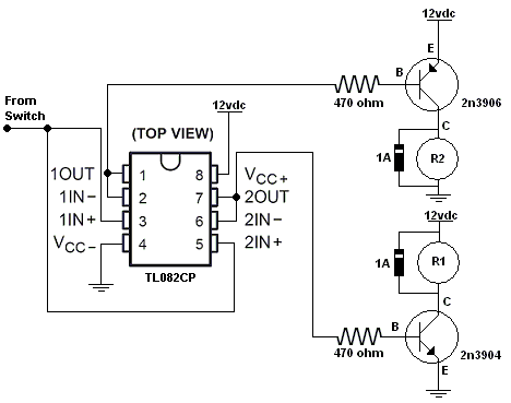
I built the op amp circuit and it worked!  I built it exactly as shown with no added components.

I also built the zener diode circuit and it worked as well.  However, you have to be VERY careful when picking your zener diodes.  I only had 5V zeners on hand so I used them.  At 12vdc the output of the NPN would latch on and stay on until I activated the PNP.  I slowly turned the voltage down and around 8.8vdc things started working as expected.  So, I would assume that a 6v zener would only work at 10.5vdc or below.  To get up to automotive range (14.8vdc) you would need around a 9v zener to work correctly.  The low side of the input voltage with the 5v zeners was 6.5vdc.  Below that the NPN wouldn't trigger.

Thank you dualsport for not only posting the diagram but explaining how it works.  I've learned quite a bit on this thread.

Jon to answer you question about multiplexing you can use the op amps to set up a comparator circuit.  You will need one op amp to be a low threshold and one to be a high threshold.  You can run the outputs of both comparators through a NAND gate - if both inputs are off the gate will turn on to drive a transistor to drive a relay.  I've done this before for a car and it worked, although it's far from elegent.  A better solution would include an ADC and a microcontroller - far less parts count and much more flexibility.

Kevin Pierson
dualsport 
Silver - Posts: 983
Silver spacespace
Joined: September 27, 2005
Location: United States
Posted: May 06, 2009 at 11:53 PM / IP Logged  
Yeah, the gain of the transistor driver will amplify any current that goes through the zener diodes, so the zener voltage has to be at *least* 1/2 of the supply voltage or more. The 5V x 2 you tried is less than the supply voltage, so they'll pass a large amount of current, same as if they were just shorted together and weren't there.
Any conduction at all through the zeners will be amplified by the transistors and drive the relay on.
Putting resistors between the base and emitters to bias it toward cutoff will also help make sure the transistors are turned off in standby.
All sorts of things to tweak it as needed, but that's basically the idea, the zener diode is like a blowoff valve that only opens up when there's enough pressure, and blocks any flow below the lower pressures. So putting them inline like that so that they both add up to a value greater than the supply voltage will act like an open circuit.
Then when the input is applied from the midpoint, a higher voltage than the breakdown is put across the diodes, and they open up to allow the current to flow. Then it allows the relay or transistor to be turned on.
You can try eliminating the transistors if the input signal can drive the relays directly. If your relays are sensitive enough to energize with 6V, it should work. You might give that a quick try since you have it built up already-
dualsport 
Silver - Posts: 983
Silver spacespace
Joined: September 27, 2005
Location: United States
Posted: May 07, 2009 at 12:26 AM / IP Logged  
KPierson wrote:

banging my head, 1 wire, 2 functions - Page 6 -- posted image.

Out of curiosity, on this, when the input is left open and allowed to float, doesn't the output follow it and result in the relays turning on the same way it does in the direct transistor drive circuit?
I would have thought whatever voltage it floats to would end up turning on one or both of the relays? Even if it happened to float to exactly the midpoint and put 6V out, it would turn on both relays.
That's why I was wondering if there was supposed to be a condition where both relays are off and in standby.
KPierson 
Platinum - Posts: 3,527
Platinum spaceThis member consistently provides reliable informationspace
Joined: April 14, 2005
Location: Ohio, United States
Posted: May 07, 2009 at 5:27 AM / IP Logged  

The problem with putting pull up/down resistors on the input is that if you do, you again lose your isolation (as you would have both a pull up and a pull down resistor going from battery to ground, which would give you exactly 1/2 your battery voltage in the standby condition on both outputs.

One thing I did observe is that if the inputs of the op amp were disconnected the relays would turn on.  Installing resistors would obviously fix this situation.  However, when I connected both op amp inputs together both relays turned off and then the circuit operated as expected.  I should have measured the output voltage in the standby condition but I didn't. 

Kevin Pierson
djfearny2 
Silver - Posts: 810
Silver spaceThis member has made a donation to the12volt.com. Click here for more info.spacespace
Joined: September 23, 2002
Location: United States
Posted: May 07, 2009 at 9:10 AM / IP Logged  
ok so here is my status
It is working basically.
I had the Transitors wired opposite so switched that, and now here is what im getting
1- have to diode isolate inputs.
2- negative output not strong enough to control a relay.
3- the possitive output is resting at possitive which is ok seeing as i can just wire the relay differently,.
now as far as the negative goes, it is strong enough to control the shifter without a relay which is better as I prefer not to here the relay clicking when shifting since i use the feature often. plus I have to diode isolate the output to the shifter as well or it disables the whole manual shifting.
However if i change the resistance value can that increase the output power if needed?
Jon
Installer/Help Technician
---coral springs florida---
mecp certification is not always needed. I have it and it has not helped me out at all. my experience out shines it.
KPierson 
Platinum - Posts: 3,527
Platinum spaceThis member consistently provides reliable informationspace
Joined: April 14, 2005
Location: Ohio, United States
Posted: May 07, 2009 at 10:38 AM / IP Logged  

How did you end up wiring it?  Make sure you are hooking the PNP and NPN up correctly - if you reverse the collector and emitter it won't work correctly.

You shouldn't have to change any resistor values, the 470ohm should be more then enough to bias the transistor.

djfearny2 wrote:
ok so here is my status
It is working basically.
I had the Transitors wired opposite so switched that, and now here is what im getting
1- have to diode isolate inputs.
2- negative output not strong enough to control a relay.
3- the possitive output is resting at possitive which is ok seeing as i can just wire the relay differently,.
now as far as the negative goes, it is strong enough to control the shifter without a relay which is better as I prefer not to here the relay clicking when shifting since i use the feature often. plus I have to diode isolate the output to the shifter as well or it disables the whole manual shifting.
However if i change the resistance value can that increase the output power if needed?

Kevin Pierson
djfearny2 
Silver - Posts: 810
Silver spaceThis member has made a donation to the12volt.com. Click here for more info.spacespace
Joined: September 23, 2002
Location: United States
Posted: May 07, 2009 at 11:38 AM / IP Logged  
what will happen if i have the c and e reversed?
I am almost curtain i have them wired all correctly.
Jon
Installer/Help Technician
---coral springs florida---
mecp certification is not always needed. I have it and it has not helped me out at all. my experience out shines it.
djfearny2 
Silver - Posts: 810
Silver spaceThis member has made a donation to the12volt.com. Click here for more info.spacespace
Joined: September 23, 2002
Location: United States
Posted: May 07, 2009 at 11:40 AM / IP Logged  
I followed the diagram On the back of the radio shack packaging to determine c & E
Jon
Installer/Help Technician
---coral springs florida---
mecp certification is not always needed. I have it and it has not helped me out at all. my experience out shines it.
djfearny2 
Silver - Posts: 810
Silver spaceThis member has made a donation to the12volt.com. Click here for more info.spacespace
Joined: September 23, 2002
Location: United States
Posted: May 07, 2009 at 11:40 AM / IP Logged  
should both wires be resting at nothing or the opposite polarity of the output ?
Jon
Installer/Help Technician
---coral springs florida---
mecp certification is not always needed. I have it and it has not helped me out at all. my experience out shines it.
KPierson 
Platinum - Posts: 3,527
Platinum spaceThis member consistently provides reliable informationspace
Joined: April 14, 2005
Location: Ohio, United States
Posted: May 07, 2009 at 3:32 PM / IP Logged  

How did you end up wiring it?  There are several different schematics posted.

When you asked about "both wires" resting what two wires are you talking about?  If you are talking about the wires comming from the collectors of the transistors to the relays then the answer is yes.  They will rest at nothing but the opposite polarity of the the output.  This is because you are reading voltage through the coil of the relay.  The actual transistor, with the relay disconnected, should rest at open.  With the relay hooked up the collector should show whatever is on the other side of the coil.

Kevin Pierson
Page of 7

  Printable version Printable version Post ReplyPost New Topic
You cannot post new topics in this forum
You cannot reply to topics in this forum
You cannot delete your posts in this forum
You cannot edit your posts in this forum
You cannot create polls in this forum
You cannot vote in polls in this forum

  •  
Search the12volt.com
Follow the12volt.com Follow the12volt.com on Facebook
Thursday, March 28, 2024 • Copyright © 1999-2024 the12volt.com, All Rights Reserved Privacy Policy & Use of Cookies
Disclaimer: *All information on this site ( the12volt.com ) is provided "as is" without any warranty of any kind, either expressed or implied, including but not limited to fitness for a particular use. Any user assumes the entire risk as to the accuracy and use of this information. Please verify all wire colors and diagrams before applying any information.

Secured by Sectigo
the12volt.com spacer
Support the12volt.com
Top
the12volt.com spacer