the12volt.com spacer
icon

banging my head, 1 wire, 2 functions


Post ReplyPost New Topic
< Prev Topic Next Topic >
dualsport 
Silver - Posts: 983
Silver spacespace
Joined: September 27, 2005
Location: United States
Posted: May 03, 2009 at 10:56 PM / IP Logged  
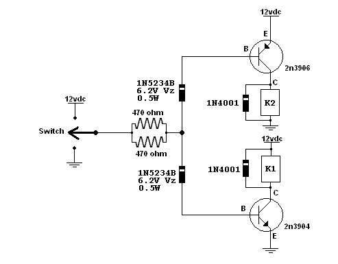
banging my head, 1 wire, 2 functions - Page 5 -- posted image.
You can put your two 470 ohm resistors in parallel to maintain the same current to make sure you drive the transistors into saturation. If your relays require a higher current you should decrease the resistor value to get more drive current.
Measure the Vce voltage across the transistor that's turned on to make sure it's driven fully on, should be close to zero volts.
KPierson 
Platinum - Posts: 3,527
Platinum spaceThis member consistently provides reliable informationspace
Joined: April 14, 2005
Location: Ohio, United States
Posted: May 04, 2009 at 9:57 AM / IP Logged  

dualsport wrote:
banging my head, 1 wire, 2 functions - Page 5 -- posted image.
You can put your two 470 ohm resistors in parallel to maintain the same current to make sure you drive the transistors into saturation. If your relays require a higher current you should decrease the resistor value to get more drive current.
Measure the Vce voltage across the transistor that's turned on to make sure it's driven fully on, should be close to zero volts.

You should be able to leave the resistor right at 470 as long as it is a 12vdc system.  These transistors (from memory) have a gain of 35 so saturation really isn't an issue (theoretical output at 12vdc and 470 ohms is ~900mA).

Can you explain how the top PNP transistor will be biased through the zener?  I understand that the bottom zener will start conducting after the break down voltage is passed (6v in this case) but how is the top zener going to start conducting the (-) signal required to bias the PNP 3906?  Also, if you have 12vdc feeding from the collector of the 3906 to the base won't it avalanch both diodes anyway?  I'll have to add this to my list of circuits to build to see if it works out - I must say I'm skeptical at this point.

Kevin Pierson
dualsport 
Silver - Posts: 983
Silver spacespace
Joined: September 27, 2005
Location: United States
Posted: May 04, 2009 at 10:50 AM / IP Logged  

It's the same thing with the top zener when the input being supplied is a ground signal.  As long as the voltage across the zener is greater than the breakdown voltage, it'll start to conduct and pass current through.

For the top zener, the voltage being applied is 12V in the standby condition, and then when the ground signal is applied, the anode of the diode tries to go to zero through the biasing resistor, so it'll conduct and maintain the 6.2V across it.   Pretty much like ground switching a relay with the other side of the coil at 12V vs. switching it on by applying 12V to it with the other side of the coil grounded.

Because the zener drops the voltage by about 6V, then you would need to use 6V as the driving source for calculating the bias resistor requirement.  If the gain is 35, and the relay needs 200mA, then 6V would be ample for the base current.

Since you already built up the original circuit it should be easy enough to try out.  Give it a whirl and see- mouser has the diodes for pennies- :)

If you have a very high supply voltage, you may want to use a higher zener voltage to prevent conduction in the standby condtion (basically the two zener voltages added up should be greater than the supply voltage)

dualsport 
Silver - Posts: 983
Silver spacespace
Joined: September 27, 2005
Location: United States
Posted: May 06, 2009 at 9:21 AM / IP Logged  
Are we giving up on this one?
A resistance added between the base and emitter of the transistors will help bias it to off in the standby mode, if you're finding that to be a problem.
djfearny2 
Silver - Posts: 810
Silver spaceThis member has made a donation to the12volt.com. Click here for more info.spacespace
Joined: September 23, 2002
Location: United States
Posted: May 06, 2009 at 8:51 PM / IP Logged  
I am waiting for the zener diodes to arrive.
and I am about to try the first circuit as described earlier in the thread/
Jon
Installer/Help Technician
---coral springs florida---
mecp certification is not always needed. I have it and it has not helped me out at all. my experience out shines it.
djfearny2 
Silver - Posts: 810
Silver spaceThis member has made a donation to the12volt.com. Click here for more info.spacespace
Joined: September 23, 2002
Location: United States
Posted: May 06, 2009 at 9:55 PM / IP Logged  
first setup with op chip failed
does not control relays. even with changing resistance.
Jon
Installer/Help Technician
---coral springs florida---
mecp certification is not always needed. I have it and it has not helped me out at all. my experience out shines it.
djfearny2 
Silver - Posts: 810
Silver spaceThis member has made a donation to the12volt.com. Click here for more info.spacespace
Joined: September 23, 2002
Location: United States
Posted: May 06, 2009 at 9:57 PM / IP Logged  
does any one know how to do a multiplex resited ground network??
Jon
Installer/Help Technician
---coral springs florida---
mecp certification is not always needed. I have it and it has not helped me out at all. my experience out shines it.
i am an idiot 
Platinum - Posts: 13,667
Platinum spaceThis member consistently provides reliable informationspace
Joined: September 21, 2006
Location: Louisiana, United States
Posted: May 06, 2009 at 10:13 PM / IP Logged  
Did you try the 2 relays and diodes on the first page of this thread?
djfearny2 
Silver - Posts: 810
Silver spaceThis member has made a donation to the12volt.com. Click here for more info.spacespace
Joined: September 23, 2002
Location: United States
Posted: May 06, 2009 at 10:24 PM / IP Logged  
yes i did and what happened was the resting ground would activate the other relay.
Jon
Installer/Help Technician
---coral springs florida---
mecp certification is not always needed. I have it and it has not helped me out at all. my experience out shines it.
dualsport 
Silver - Posts: 983
Silver spacespace
Joined: September 27, 2005
Location: United States
Posted: May 06, 2009 at 10:32 PM / IP Logged  
You need the zener diodes to provide an inactive zone where the relays are not energized.
If you want to drive the relays directly, you can simply put the zeners on the circuit as shown above, delete the 470k input resistor, and run the ends of the zeners to your relay coils. Make believe the transistors are relays, top one configured to ground switch, and the bottom one configured to high switch.
Your input signal has to provide enough current to drive the relays, and you have to make sure the relays are able to switch with 6V. If they don't, then you can just get 6V relays instead of the 12V.
That'd be the simplest if the circuits are looking too complicated.
Page of 7

  Printable version Printable version Post ReplyPost New Topic
You cannot post new topics in this forum
You cannot reply to topics in this forum
You cannot delete your posts in this forum
You cannot edit your posts in this forum
You cannot create polls in this forum
You cannot vote in polls in this forum

  •  
Search the12volt.com
Follow the12volt.com Follow the12volt.com on Facebook
Thursday, April 25, 2024 • Copyright © 1999-2024 the12volt.com, All Rights Reserved Privacy Policy & Use of Cookies
Disclaimer: *All information on this site ( the12volt.com ) is provided "as is" without any warranty of any kind, either expressed or implied, including but not limited to fitness for a particular use. Any user assumes the entire risk as to the accuracy and use of this information. Please verify all wire colors and diagrams before applying any information.

Secured by Sectigo
the12volt.com spacer
Support the12volt.com
Top
the12volt.com spacer