the12volt.com spacer
icon

banging my head, 1 wire, 2 functions


Post ReplyPost New Topic
< Prev Topic Next Topic >
dualsport 
Silver - Posts: 983
Silver spacespace
Joined: September 27, 2005
Location: United States
Posted: May 02, 2009 at 10:10 PM / IP Logged  
Is there supposed to be a quiescent condition where neither relay is on?
If the input is left floating what is going to happen with the relays?
dualsport 
Silver - Posts: 983
Silver spacespace
Joined: September 27, 2005
Location: United States
Posted: May 02, 2009 at 10:25 PM / IP Logged  
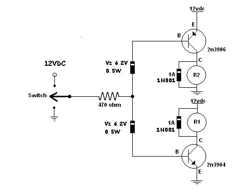
I'd suggest adding zener diodes on the original transistor drive circuit to provide isolation in the inactive condition where neither relay is supposed to be energized.
Put them in series with the base of the transistors, and put the base resistor in the input from the steering wheel wire.
When the input is open, the two zener diodes in series will not conduct (select a value of 6V or so), since they'll below 12V.
When you have an active input of 12V or ground, the corresponding zener will begin to conduct since it'll have 12V across the single zener, and provide the current to the transistor driver stage.
t&t tech 
Platinum - Posts: 2,608
Platinum spacespace
Joined: October 05, 2008
Location: Trinidad and Tobago
Posted: May 02, 2009 at 11:09 PM / IP Logged  
at the risk of sounding stupid i'm gonna ask a question, feel free to criticize me, would wiring the trigger with the same polarity make this problem go away, since he's using relays i mean, does he really need a negative and a positive signal, if he were to just use a straight negative signal to activate both relays one would be going negative to negative and the other inverting from negative to positive, or the other way positive signal triggering both relays, or would there still be feedback ?, or is this too simple and i don't know what i'm saying, again feel free to criticize.
commit your way to jehovah and he will act in your behalf. psalms 37:5
dualsport 
Silver - Posts: 983
Silver spacespace
Joined: September 27, 2005
Location: United States
Posted: May 02, 2009 at 11:48 PM / IP Logged  
There's two different functions he's trying to control with a single wire, and probably aren't supposed to happen at the same time.
To individually control the two functions means there has to be a different signal to trigger each one. In this case, one is a +12V positive signal, and the other is a negative going ground switch signal.
When neither one is active, it's presumed to be just left as an open circuit.
t&t tech 
Platinum - Posts: 2,608
Platinum spacespace
Joined: October 05, 2008
Location: Trinidad and Tobago
Posted: May 03, 2009 at 2:00 PM / IP Logged  
oh, i now re read, sorrybanging my head, 1 wire, 2 functions - Page 4 -- posted image.
commit your way to jehovah and he will act in your behalf. psalms 37:5
djfearny2 
Silver - Posts: 810
Silver spaceThis member has made a donation to the12volt.com. Click here for more info.spacespace
Joined: September 23, 2002
Location: United States
Posted: May 03, 2009 at 6:57 PM / IP Logged  
do you have a part number for a zener diode?
Jon
Installer/Help Technician
---coral springs florida---
mecp certification is not always needed. I have it and it has not helped me out at all. my experience out shines it.
i am an idiot 
Platinum - Posts: 13,667
Platinum spaceThis member consistently provides reliable informationspace
Joined: September 21, 2006
Location: Louisiana, United States
Posted: May 03, 2009 at 7:46 PM / IP Logged  

Zener diodes are rated for voltage and wattage.  I have no idea what you need for what he is suggesting.  But following should help to get a number when you get a voltage and wattage.

http://www.fairchildsemi.com/sitesearch/fsc.jsp?command=eq&attr1=AAAFamily&attr2=Zener+Diode

dualsport 
Silver - Posts: 983
Silver spacespace
Joined: September 27, 2005
Location: United States
Posted: May 03, 2009 at 8:11 PM / IP Logged  
No requirement for wattage, it'll be limited by the base resistor that'll be inline, and non conducting in the standby condition.
They're typically 1/2W, which would be fine.
Like I said, a breakdown voltage of about 6V would do. The 6.2V one shown on the fairchild listing should be suitable.
Check mouser.com for quantities under 1000 pcs.
dualsport 
Silver - Posts: 983
Silver spacespace
Joined: September 27, 2005
Location: United States
Posted: May 03, 2009 at 8:43 PM / IP Logged  
Since it looks like it wasn't clear what I was thinking of, here's a diagram based on Kevin's original circuit-
banging my head, 1 wire, 2 functions - Page 4 -- posted image.
Relay R1 will switch on with a 12V input, and R2 will energize with a ground input.
When the input is left open, neither relay will be on.
i am an idiot 
Platinum - Posts: 13,667
Platinum spaceThis member consistently provides reliable informationspace
Joined: September 21, 2006
Location: Louisiana, United States
Posted: May 03, 2009 at 8:51 PM / IP Logged  
The Zener diodes are 1N5234B   The other diodes pictured are 1N4001s
Page of 7

  Printable version Printable version Post ReplyPost New Topic
You cannot post new topics in this forum
You cannot reply to topics in this forum
You cannot delete your posts in this forum
You cannot edit your posts in this forum
You cannot create polls in this forum
You cannot vote in polls in this forum

  •  
Search the12volt.com
Follow the12volt.com Follow the12volt.com on Facebook
Thursday, April 25, 2024 • Copyright © 1999-2024 the12volt.com, All Rights Reserved Privacy Policy & Use of Cookies
Disclaimer: *All information on this site ( the12volt.com ) is provided "as is" without any warranty of any kind, either expressed or implied, including but not limited to fitness for a particular use. Any user assumes the entire risk as to the accuracy and use of this information. Please verify all wire colors and diagrams before applying any information.

Secured by Sectigo
the12volt.com spacer
Support the12volt.com
Top
the12volt.com spacer