the12volt.com spacer
icon

banging my head, 1 wire, 2 functions


Post ReplyPost New Topic
< Prev Topic Next Topic >
KPierson 
Platinum - Posts: 3,527
Platinum spaceThis member consistently provides reliable informationspace
Joined: April 14, 2005
Location: Ohio, United States
Posted: April 28, 2009 at 9:00 PM / IP Logged  

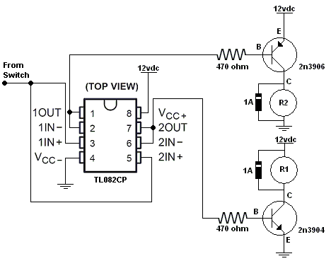
I don't know how involved you are willing to get with this, but I have another idea that involves using an op amp as a two voltage followers.  The outputs of the op amps can then drive the transistors above.

Have you tried the relay diagram with the diodes?  If that works that would be quite a bit simpler.

Kevin Pierson
i am an idiot 
Platinum - Posts: 13,667
Platinum spaceThis member consistently provides reliable informationspace
Joined: September 21, 2006
Location: Louisiana, United States
Posted: April 28, 2009 at 9:11 PM / IP Logged  
If you do try the relays, the numbers are correct on the relays.  However the layout is not correct.  Do not make the circuit look as it does in the picture.
djfearny2 
Silver - Posts: 810
Silver spaceThis member has made a donation to the12volt.com. Click here for more info.spacespace
Joined: September 23, 2002
Location: United States
Posted: April 28, 2009 at 10:56 PM / IP Logged  
im into it until it is accomplished.
I have a dodge and they are notorious for multiplex systems. one wire with multible functions via ground resistance. I can wire the switches for anything i need or want. Do you or anyone know of a system or setup that can be done to create a multiplex system.
Jon
Installer/Help Technician
---coral springs florida---
mecp certification is not always needed. I have it and it has not helped me out at all. my experience out shines it.
djfearny2 
Silver - Posts: 810
Silver spaceThis member has made a donation to the12volt.com. Click here for more info.spacespace
Joined: September 23, 2002
Location: United States
Posted: April 28, 2009 at 10:58 PM / IP Logged  
I know the pin outs on relays without even thinking about it anymore so I read it as numbers anyway. BUt i did try it and didnt get anywhere. will again try anything.,
Jon
Installer/Help Technician
---coral springs florida---
mecp certification is not always needed. I have it and it has not helped me out at all. my experience out shines it.
KPierson 
Platinum - Posts: 3,527
Platinum spaceThis member consistently provides reliable informationspace
Joined: April 14, 2005
Location: Ohio, United States
Posted: April 29, 2009 at 6:03 AM / IP Logged  

djfearny2 wrote:
im into it until it is accomplished.
I have a dodge and they are notorious for multiplex systems. one wire with multible functions via ground resistance. I can wire the switches for anything i need or want. Do you or anyone know of a system or setup that can be done to create a multiplex system.

Multiplexing gets a bit more involved and can be done in several ways.  For a voltage multiplex you can use a microcontroller with analog to digital converter or you can use op amps set up as voltage comparators.  I've personally done it both ways and it worked both ways.  When I went the op amp route I used to op amps for each multiplex input and created a voltage "window".

Since you are only using battery voltage and ground I think it can be done with one op amp chip (with multiple op amps on it).  I'll try to draw something up later today.

Kevin Pierson
djfearny2 
Silver - Posts: 810
Silver spaceThis member has made a donation to the12volt.com. Click here for more info.spacespace
Joined: September 23, 2002
Location: United States
Posted: April 29, 2009 at 7:16 AM / IP Logged  
thnanks again if possible please include part numbers.
Jon
Installer/Help Technician
---coral springs florida---
mecp certification is not always needed. I have it and it has not helped me out at all. my experience out shines it.
djfearny2 
Silver - Posts: 810
Silver spaceThis member has made a donation to the12volt.com. Click here for more info.spacespace
Joined: September 23, 2002
Location: United States
Posted: April 30, 2009 at 1:44 PM / IP Logged  
im guessing no luck or time.
Jon
Installer/Help Technician
---coral springs florida---
mecp certification is not always needed. I have it and it has not helped me out at all. my experience out shines it.
KPierson 
Platinum - Posts: 3,527
Platinum spaceThis member consistently provides reliable informationspace
Joined: April 14, 2005
Location: Ohio, United States
Posted: April 30, 2009 at 2:44 PM / IP Logged  

banging my head, 1 wire, 2 functions - Page 3 -- posted image.

I would give this a shot.  The op amp (available at Radioshack stores) should provide isolation between the transistor bases.  The op amp will be set up as a "voltage follower" on both channels and will output whatever  you put in to it.  So, Pin 1 and Pin 7 will mimic your wire coming from the steering wheel.  The seperate, isolated channels should stop any feedback.

Kevin Pierson
djfearny2 
Silver - Posts: 810
Silver spaceThis member has made a donation to the12volt.com. Click here for more info.spacespace
Joined: September 23, 2002
Location: United States
Posted: April 30, 2009 at 10:40 PM / IP Logged  
can you tell me how i determine the propper pin outs on the op chip. There is no significant marking except a dot more or less to determine orientation.
Jon
Installer/Help Technician
---coral springs florida---
mecp certification is not always needed. I have it and it has not helped me out at all. my experience out shines it.
i am an idiot 
Platinum - Posts: 13,667
Platinum spaceThis member consistently provides reliable informationspace
Joined: September 21, 2006
Location: Louisiana, United States
Posted: April 30, 2009 at 10:43 PM / IP Logged  
The Dot is pin 1.   Also, the horseshoe shaped notch in the top of the picture above indicates pin 1.  All integrated circuits have one or both of the markings described.
Page of 7

  Printable version Printable version Post ReplyPost New Topic
You cannot post new topics in this forum
You cannot reply to topics in this forum
You cannot delete your posts in this forum
You cannot edit your posts in this forum
You cannot create polls in this forum
You cannot vote in polls in this forum

  •  
Search the12volt.com
Follow the12volt.com Follow the12volt.com on Facebook
Friday, April 19, 2024 • Copyright © 1999-2024 the12volt.com, All Rights Reserved Privacy Policy & Use of Cookies
Disclaimer: *All information on this site ( the12volt.com ) is provided "as is" without any warranty of any kind, either expressed or implied, including but not limited to fitness for a particular use. Any user assumes the entire risk as to the accuracy and use of this information. Please verify all wire colors and diagrams before applying any information.

Secured by Sectigo
the12volt.com spacer
Support the12volt.com
Top
the12volt.com spacer