the12volt.com spacer
icon

impossible to find wire diagram, 96 quest


Post ReplyPost New Topic
< Prev Topic Next Topic >
tak4 
Copper - Posts: 76
Copper spacespace
Joined: January 31, 2008
Location: Hawaii, United States
Posted: June 27, 2009 at 12:41 AM / IP Logged  
Yes the rear seat has controls.
I saw that same diagram on a site. But my color wires don't match thoes. (ex. I don't have a GREEN/ violet.)
i am an idiot 
Platinum - Posts: 13,667
Platinum spaceThis member consistently provides reliable informationspace
Joined: September 21, 2006
Location: Louisiana, United States
Posted: June 27, 2009 at 1:19 AM / IP Logged  

Are you sure that all 3 of those plugs were plugged into the back of the radio?   Can you take a picture of the back of the radio and post it?

Have you looked in the center console to see if you find a factory amp?

Let's Go Brandon Brown. Congratulations on your first Xfinity Series Win. LGBFJB
tak4 
Copper - Posts: 76
Copper spacespace
Joined: January 31, 2008
Location: Hawaii, United States
Posted: June 27, 2009 at 2:01 AM / IP Logged  

Yes It seems that there is a factory amp in the trunk.

Yes im sure that all of them plugged into the back. I will take a picture and post it, it might be low quality as i will have to take it with my phone.

i am an idiot 
Platinum - Posts: 13,667
Platinum spaceThis member consistently provides reliable informationspace
Joined: September 21, 2006
Location: Louisiana, United States
Posted: June 27, 2009 at 2:07 AM / IP Logged  
Do the wire colors on the factory amp match the colors of the diagrams you have found?   A phone pic should do just fine.
tak4 
Copper - Posts: 76
Copper spacespace
Joined: January 31, 2008
Location: Hawaii, United States
Posted: June 27, 2009 at 2:30 AM / IP Logged  

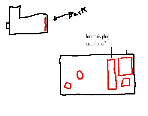
I tried to take a pic with my phone but I couldnt email to myself for some reason. so i drew (a ugly picture) of the back of the radio.

The two circle are where the radio thing and this only thing went into.

and the others are the three harnesses.

[IMG]https://img.photobucket.com/albums/v520/02Sakura/radio.jpg[/IMG]

i am an idiot 
Platinum - Posts: 13,667
Platinum spaceThis member consistently provides reliable informationspace
Joined: September 21, 2006
Location: Louisiana, United States
Posted: June 27, 2009 at 3:12 AM / IP Logged  

i am an idiot wrote:
Do the wire colors on the factory amp match the colors of the diagrams you have found? 

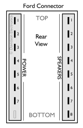
Pay attention to only the left plug in the following diagram.  You have an amplifier in that vehicle, chances are you are going to have to bypass the amplifier if you want it to be engine noise free.

impossible to find wire diagram, 96 quest - Page 2 -- posted image.

POWER

1=Permanent Live
2=Ground this pin
3=IGN live
4=Illumination
5=N/C
6=Ground
7=Electric aerial

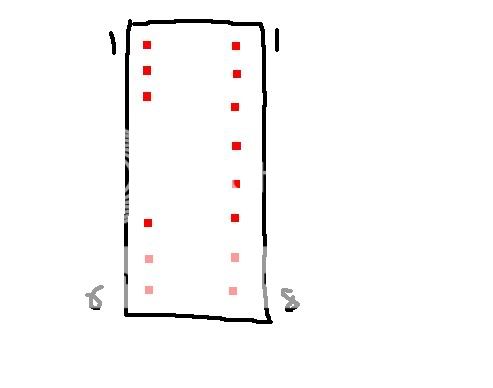
Following is the pic you posted, has anyone ever seen an amp preamp plug with 12 wires on it.   I am sure it has to go to the rear controls.  You do know you are probably going to lose the rear controls if you do this.

impossible to find wire diagram, 96 quest - Page 2 -- posted image.Disregard the question about the 7 pins.

tak4 
Copper - Posts: 76
Copper spacespace
Joined: January 31, 2008
Location: Hawaii, United States
Posted: June 27, 2009 at 5:18 AM / IP Logged  

impossible to find wire diagram, 96 quest - Page 2 -- posted image.

Yes my amp harness looks like your picture one side 1-6 and the other 1-8

1.Orange

2.Black
3. White
4. blank
5.blank
6.blank

1-8 all the speaker wires.

How do I bypass the amp? Do I tap all the power, Ignition, ground, and speaker wires from the amp harness instead of the harness that pluged into the factory radio?

if so how do I knoe which speaker wire is positive and what it negative?

I know the 1-8 goes in pairs like 1&2 is Front left, 3&4 is Front right, etc

but does it also go positive and negative, positive and negative? or negative and positive, negative and positive?

its ok if i cant controll it in the back, the back controls stopped working long ago anyways. haha

i am an idiot 
Platinum - Posts: 13,667
Platinum spaceThis member consistently provides reliable informationspace
Joined: September 21, 2006
Location: Louisiana, United States
Posted: June 27, 2009 at 7:29 AM / IP Logged  
impossible to find wire diagram, 96 quest - Page 2 -- posted image.

POWER

1=Permanent Live
2=Ground this pin
3=IGN live
4=Illumination
5=N/C
6=Ground
7=Electric aerial

SPEAKERS

1=Left Front +
2=Left Front -
3=Left Rear +
4=Left Rear -
5=Right Front +
6=Right Front -
7=Right Rear +
8=Right Rear -

tak4 
Copper - Posts: 76
Copper spacespace
Joined: January 31, 2008
Location: Hawaii, United States
Posted: June 27, 2009 at 12:59 PM / IP Logged  

Ok ill give that a try.

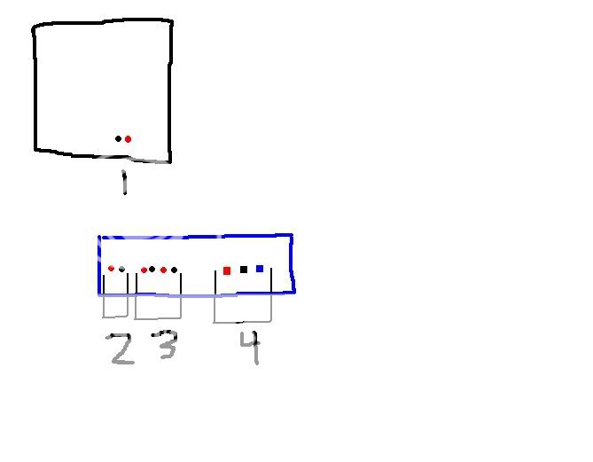
Also I I want to install my sub and amp, so I hooked it up like this

impossible to find wire diagram, 96 quest - Page 2 -- posted image.

I connect the sub (#1) to the Speaker output left + and - right [labled bridged](#3)  my right + and left - is empty.

I connect the RCA from the deck to #2 [line in] on my amp line out is emtpy
I connect Power, Ground, and P.con (#4) Power to battery, Ground close to amp, and P.con to the IGN wire of the deck.

How does that sound? correct?

i am an idiot 
Platinum - Posts: 13,667
Platinum spaceThis member consistently provides reliable informationspace
Joined: September 21, 2006
Location: Louisiana, United States
Posted: June 30, 2009 at 8:27 PM / IP Logged  
That sounds correct, assuming you have the correct terminals on the back of the radio.
Page of 3

  Printable version Printable version Post ReplyPost New Topic
You cannot post new topics in this forum
You cannot reply to topics in this forum
You cannot delete your posts in this forum
You cannot edit your posts in this forum
You cannot create polls in this forum
You cannot vote in polls in this forum

  •  
Search the12volt.com
Follow the12volt.com Follow the12volt.com on Facebook
Friday, April 26, 2024 • Copyright © 1999-2024 the12volt.com, All Rights Reserved Privacy Policy & Use of Cookies
Disclaimer: *All information on this site ( the12volt.com ) is provided "as is" without any warranty of any kind, either expressed or implied, including but not limited to fitness for a particular use. Any user assumes the entire risk as to the accuracy and use of this information. Please verify all wire colors and diagrams before applying any information.

Secured by Sectigo
the12volt.com spacer
Support the12volt.com
Top
the12volt.com spacer