the12volt.com spacer
icon

2009 Ford F-150 Door Trigger Wiring


Post ReplyPost New Topic
< Prev Topic Next Topic >
fordguy218 
Member - Posts: 32
Member spacespace
Joined: July 11, 2009
Location: Louisiana, United States
Posted: July 12, 2009 at 7:33 PM / IP Logged  
Thanks Joe. I'll check the wiring tonight and followup with the results. Much appreciated!!!!
fordguy218 
Member - Posts: 32
Member spacespace
Joined: July 11, 2009
Location: Louisiana, United States
Posted: July 12, 2009 at 8:58 PM / IP Logged  

Joe. No luck.

I'm getting a (+) output on both wires when I unlock the truck with the remote. I connected the wires with a diode as you specified and nothing either way.

With the blue wire and green wire hooked up to an LED, both LEDs light when I unlock the truck, but neither light when I lock the truck. Any suggestions???

KarTuneMan 
Platinum - Posts: 7,056
Platinum spaceThis member has made a donation to the12volt.com. Click here for more info.spaceThis member consistently provides reliable informationspace
Joined: December 14, 2004
Location: Isle Of Man
Posted: July 12, 2009 at 9:01 PM / IP Logged  

The individual door pins show a VERY low voltage reading or NOTHING when opened, and ground when closed.

They need to be isolated, and "converted" to a (POS)+ trigger to be used.

There is a diagram out there somewheres.... I don't type well enough to put it down.

fordguy218 
Member - Posts: 32
Member spacespace
Joined: July 11, 2009
Location: Louisiana, United States
Posted: July 12, 2009 at 9:07 PM / IP Logged  
So what are you saying I need to do? RELAY?
i am an idiot 
Platinum - Posts: 13,667
Platinum spaceThis member consistently provides reliable informationspace
Joined: September 21, 2006
Location: Louisiana, United States
Posted: July 12, 2009 at 9:11 PM / IP Logged  
FordGuy is talking door locks.   KarTuneMan is talking door trigger wire.
fordguy218 
Member - Posts: 32
Member spacespace
Joined: July 11, 2009
Location: Louisiana, United States
Posted: July 12, 2009 at 9:17 PM / IP Logged  

Okay. ...door triggers (right front, right rear, left front, and left rear) are wired properly to the appropriate wires and isolated using diodes... no problems there. It's just the door locks.

Let me try to explain further. Green wire to VT/GY, Blue wire to GY/YE. Diodes on each wire. Unlock displaces 0V on each wire, whereas Lock displaces 12V on each wire. Shouldn't these wires be emitting opposite charges depending on whether I lock or unlock???

fordguy218 
Member - Posts: 32
Member spacespace
Joined: July 11, 2009
Location: Louisiana, United States
Posted: July 12, 2009 at 9:19 PM / IP Logged  
ahh. the other way around.  blue to vt/gy and green to gy/ye. nothing
i am an idiot 
Platinum - Posts: 13,667
Platinum spaceThis member consistently provides reliable informationspace
Joined: September 21, 2006
Location: Louisiana, United States
Posted: July 12, 2009 at 9:40 PM / IP Logged  

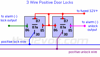
The Door locks on your vehicle are 3 wire negative.  Following is a diagram for 3 wire positive.  There are instructions in the text that tell you what to do to make it negative.  According to Audiovox, you do have the correct wires.

2009 Ford F-150 Door Trigger Wiring - Page 2 -- posted image. 3 Wire Positive Door Locks
This is one of the most common type of door lock switch configurations found in most vehicles. In most cases you will not need to add relays for this type. Most of the newer alarms and keyless entries on the market today have both positive and negative 200 ma door lock outputs that are usually capable of activating the factory relays. Should you need to add relays for a "3 wire negative" door lock system, just change both normally open terminals (87) from 12V(+) to ground. If your alarm or keyless entry has positive outputs only, you will have to connect the other side of the coils to ground  and connect your outputs as shown. The lock and unlock wires below refer to the switch wires, not the motor legs.
 
2009 Ford F-150 Door Trigger Wiring - Page 2 -- posted image.

fordguy218 
Member - Posts: 32
Member spacespace
Joined: July 11, 2009
Location: Louisiana, United States
Posted: July 12, 2009 at 9:42 PM / IP Logged  

I was just re-reading through this. I thought I wouldn't have to do this though because I'm tapping in BEFORE the relay... or am I after the relay but before the actuator???

fordguy218 
Member - Posts: 32
Member spacespace
Joined: July 11, 2009
Location: Louisiana, United States
Posted: July 12, 2009 at 9:44 PM / IP Logged  
2009 Ford F-150 Door Trigger Wiring - Page 2 -- posted image.
So if using 3-wire NEGATIVE, I'll have to wire the 87 legs to +0V GROUND. Do I have to swap the ALARM LOCK OUTPUT wires to their POSITIVE output configuration?
Page of 3

  Printable version Printable version Post ReplyPost New Topic
You cannot post new topics in this forum
You cannot reply to topics in this forum
You cannot delete your posts in this forum
You cannot edit your posts in this forum
You cannot create polls in this forum
You cannot vote in polls in this forum

  •  
Search the12volt.com
Follow the12volt.com Follow the12volt.com on Facebook
Friday, April 26, 2024 • Copyright © 1999-2024 the12volt.com, All Rights Reserved Privacy Policy & Use of Cookies
Disclaimer: *All information on this site ( the12volt.com ) is provided "as is" without any warranty of any kind, either expressed or implied, including but not limited to fitness for a particular use. Any user assumes the entire risk as to the accuracy and use of this information. Please verify all wire colors and diagrams before applying any information.

Secured by Sectigo
the12volt.com spacer
Support the12volt.com
Top
the12volt.com spacer