the12volt.com spacer
icon

viper 5901 won't rs on 98 integra


Post ReplyPost New Topic
< Prev Topic Next Topic >
tym1200 
Member - Posts: 13
Member spacespace
Joined: March 21, 2004
Posted: September 26, 2009 at 10:11 PM / IP Logged  
About the immobilizer, i have a 2000 integra and I think 2000 was the first year the immobilizers were standard. I'm not sure if there was an option for one in 98 though. It should be pretty easy to tell. If it has an immobilizer the engine will just keep cranking and not start when you try to RS without the key in the ignition.   If you need an immobilizer look into something along the lines of the DEI 556hw, used it on my 2000 teg and its perfect.
howie ll 
Pot Metal - Posts: 16,466
Pot Metal spacespace
Joined: January 09, 2007
Location: United Kingdom
Posted: September 27, 2009 at 12:40 AM / IP Logged  
It's because you have to break the pink  wire. In the clutch left alone position, that pink goes to ground. When pedal is depressed, the circuit is opened enabling the car to be depressed. The simple answer would be to remove that switch completely and see if anything else is affected when the vehicle is running and driving. The correct answer would be to do the following:- status output from R/S to relay 85, ignition via 3amp fuse (use the BLACK / YELLOW from switch to where you joined your R/S Ignition 1 wire), to 86,  cut pink from switch to 3o and other side to 87a.
KarTuneMan 
Platinum - Posts: 7,056
Platinum spaceThis member has made a donation to the12volt.com. Click here for more info.spaceThis member consistently provides reliable informationspace
Joined: December 14, 2004
Location: Isle Of Man
Posted: September 27, 2009 at 12:56 AM / IP Logged  

Your picture of the clutch switch was cool.... but!

Follow those wires up to the clutch relay in te dash, there you will find a wire the same color as the starter wire.

Put your remote start output on THAT wire. I do not know if you need the starter wire on the ign. harness even connected.

gpspro 
Member - Posts: 15
Member spacespace
Joined: April 08, 2009
Posted: September 27, 2009 at 1:48 AM / IP Logged  
Interesting...thanks for your advice KarTuneMan. Before doing what you have just suggested, I have to get back to howie II about the clutch switch as it still doesn't make sense to me. Why did I have to depress the clutch pedal even after the plug that connects to the clutch switch was removed in order to start the engine with the key? If I don't press the clutch pedal, the engine won't start regardless if the clutch switch is connected or not. That makes me believe that there maybe another switch somewhere that also controls the the same circuit???
gpspro 
Member - Posts: 15
Member spacespace
Joined: April 08, 2009
Posted: September 27, 2009 at 3:03 AM / IP Logged  
This is to illustrate what I said above.
viper 5901 won't rs on 98 integra - Page 2 -- posted image.
howie ll 
Pot Metal - Posts: 16,466
Pot Metal spacespace
Joined: January 09, 2007
Location: United Kingdom
Posted: September 27, 2009 at 6:22 AM / IP Logged  
Follow KTM's instructions, he's THE Honda expert  forget about the clutch and go to the BLACK/ white wire he mentions. His word is GOSPEL on Hondas I'm only the BMW man.
gpspro 
Member - Posts: 15
Member spacespace
Joined: April 08, 2009
Posted: September 28, 2009 at 2:06 AM / IP Logged  
Thanks howie II.
Hey KTM, I couldn't find any clutch relay. Did you mean a Starter Cut Relay instead? If so, would you suggest that I connect the Starter Output (H3/4-Violet) to BLACK/ White at the Starter Cut Relay as follows:
viper 5901 won't rs on 98 integra - Page 2 -- posted image.
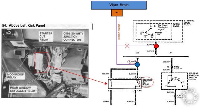
So what I should do is to disconnect the Red dot and connect the Violet wire to the BLUE dot as shown in the diagram above, correct?
moonliter 
Copper - Posts: 322
Copper spacespace
Joined: February 28, 2007
Location: Canada
Posted: September 28, 2009 at 10:42 AM / IP Logged  

The red dot & blue dot shown on the diagram is actually the same BLACK/ white wire. You should run the starter output (H3/4- violet) directly to the starter cut relay BLACK/ red wire which is on terminal 3. terminal 4 (blue/black) of the starter cut relay goes to clutch interlock switch then to ground (black).

On your car, there should be 2 clutch switches if it comes with a cruise control. That explains why it didn't work b/c you were working on the wrong clutch switch.

gpspro 
Member - Posts: 15
Member spacespace
Joined: April 08, 2009
Posted: September 29, 2009 at 12:48 AM / IP Logged  
Thank you moonliter. Yes, you're right. This car has a cruise control, a clutch switch and a clutch interlock switch. And yes, terminal 4 goes to the clutch interlock switch directly. Terminal 3 actually connects to the BLACK/ White at the starter solenoid. So by connecting the Violet to terminal 3, you are essentially connecting it to the starter solenoid directly. So looks like you've been working on Integra Generation 3 before. Is that all I have to do? and no clutch bypass is needed for my car? Could you kindly double-check my connections (at the start of this post) to see if I missed anything please before I start to reconnect my Violet wire?
moonliter 
Copper - Posts: 322
Copper spacespace
Joined: February 28, 2007
Location: Canada
Posted: September 30, 2009 at 3:26 AM / IP Logged  

I try to attach a pdf file re : 98 Integra starting circuit but the file was too big. If you pm me your email address,

I can send over for you to review.

Heavy gauge connector:

H3/6 & 9 to 12 volt constant ---- white wire at the ign sw harness
H3/3 to accessory ---- yellow wire at the ign sw harness
H3/1 to ignitin 1 ---- BLACK / YELLOW at the ign sw harness
H3/4 to starter ---- blue/red bypassing the starter cut relay ( clutch bypass relay if you want to call it )
H3/2, 7 & 8 are not needed as your car doesn't have ignition 2.

E- brake & door trigger (-) lt.GREEN/ red must be connected for manual car

I believed you had tach connected, hood switch, door lock/unlock wires should be straight forward.

Page of 4

  Printable version Printable version Post ReplyPost New Topic
You cannot post new topics in this forum
You cannot reply to topics in this forum
You cannot delete your posts in this forum
You cannot edit your posts in this forum
You cannot create polls in this forum
You cannot vote in polls in this forum

  •  
Search the12volt.com
Follow the12volt.com Follow the12volt.com on Facebook
Monday, April 29, 2024 • Copyright © 1999-2024 the12volt.com, All Rights Reserved Privacy Policy & Use of Cookies
Disclaimer: *All information on this site ( the12volt.com ) is provided "as is" without any warranty of any kind, either expressed or implied, including but not limited to fitness for a particular use. Any user assumes the entire risk as to the accuracy and use of this information. Please verify all wire colors and diagrams before applying any information.

Secured by Sectigo
the12volt.com spacer
Support the12volt.com
Top
the12volt.com spacer