the12volt.com spacer
icon

2010 ford fusion, viper 5901


Post ReplyPost New Topic
< Prev Topic Next Topic >
monty862 
Copper - Posts: 116
Copper spaceThis member has made a donation to the12volt.com. Click here for more info.spacespace
Joined: December 10, 2009
Location: Kentucky, United States
Posted: December 13, 2009 at 1:20 AM / IP Logged  
Hi guys. I have a Viper 5901  I am installing it in a 2010 Ford Fusion. I have found a good spot to mount the main unit and thought I'd start with the Heavy gauge remote start (H3) 10 pin wiring harness first. The Viper harness diagram is as follows for the harness:                                                                                                            o H3/1 Pink (+) Ignition 1 Input / Output 
o H3/2 RED / Wh (+) Fused 30A Ignition 2  / Flex relay input 87
o H3/3 Orange (+) Accessory Output
o H3/4 Violet (+) Starter Output  (harness side of starter kill wire)
o H3/5 Green (+) Starter Input (key side of starter kill wire)
o H3/6 Red (+) Fused 30A Ignition 1 Input
o H3/7 Pink/Wh (+) Ignition 2 / Flex relay output
o H3/8 Pink/Blk (+) Flex Relay Input  87A key side (if required) of flex relay
o H3/9 RED / Blk (+) Fused 30A Accessory / starter input
o H3/10             N/C       not used
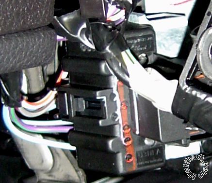
The Fusions ignition switch harness has a 7 pin plug. There are 6 wires in the 7 pin plug. The wiring diagram shows what 5 of them are. I'm not sure of the sixth.    Here is the fusion wiring diagram: 
BatteryBLUE/RED(+)IGNITION SWITCH HARNESS
2010 ford fusion, viper 5901 -- posted image.Ignition 1WHITE/ ORANGE(+)IGNITION SWITCH HARNESS
2010 ford fusion, viper 5901 -- posted image.Accessory 1VIOLET/GREEN(+)IGNITION SWITCH HARNESS
2010 ford fusion, viper 5901 -- posted image.Starter 1BLUE/WHITE(+)IGNITION SWITCH HARNESS
2010 ford fusion, viper 5901 -- posted image.Anti-Theft TypeFORD PATS® OR SECURILOCK® VEHICLE IMMOBILIZER
2010 ford fusion, viper 5901 -- posted image.Anti-Theft DescriptTHE KEY SENDS AN RF SIGNAL TO THE BCM MODULE THROUGH AN ANTENNA LOCATED AROUND THE IGNITION CYLINDER
2010 ford fusion, viper 5901 -- posted image.Key SenseBLUE/GRAY(+)IGNITION SWITCH HARNESS
I have tested and verified the function of the wires on the ignition harness. I'm still trying to figure out what the sixth wire is. The terminology that Viper uses is a little confusing to me and I am hoping you guys can steer me as to which wires from the H3 go to which wires on the ignition harness. Have no idea what a flex relay 87 is for. I believe I have to cut the Blue/White starter wire and use the Violet and Green wire from the H3 on it. I'm not certain on which accessory wire to use on the H3. I will run a wire from the battery for 12 volts if that is the best method. Hope to hear from you soon!
monty862 
Copper - Posts: 116
Copper spaceThis member has made a donation to the12volt.com. Click here for more info.spacespace
Joined: December 10, 2009
Location: Kentucky, United States
Posted: December 13, 2009 at 2:24 AM / IP Logged  
Oh, I forgot to mention I can't believe how small the wire gauge is on the Fusion ignition harness. I have installed two Bulldog systems years ago and the wires were a lot bigger on those cars. The Vipers harness wires look twice as thick!
monty862 
Copper - Posts: 116
Copper spaceThis member has made a donation to the12volt.com. Click here for more info.spacespace
Joined: December 10, 2009
Location: Kentucky, United States
Posted: December 13, 2009 at 11:56 PM / IP Logged  
I have tested the unlisted wire in the diagram.2010 Fusion- Ignition Harness-7 pin plug - pin number 3 is 12 volts constant. It appears to be grey with a brown or possibly black stripe. Don't know why its not in the diagram. Still hoping to hear from you guys on the wire connections on the H3 harness. Thanks
monty862 
Copper - Posts: 116
Copper spaceThis member has made a donation to the12volt.com. Click here for more info.spacespace
Joined: December 10, 2009
Location: Kentucky, United States
Posted: December 14, 2009 at 12:09 AM / IP Logged  
2010 ford fusion, viper 5901 -- posted image.
chev104275 
Gold - Posts: 1,424
Gold spaceThis member has been recognized as an authority in Mobile Security and Convenience. Click here for more info.spacespace
Joined: November 26, 2007
Location: Massachusetts, United States
Posted: December 14, 2009 at 6:46 AM / IP Logged  
(GY-BN) 18 CTRL MOD. - POWERTRAIN # TRANSMISSION RANGE OUTPUT PARK (TRO-P)
it goes to the floor shifter
If i Can't Install it    I Don't need it   Joe
monty862 
Copper - Posts: 116
Copper spaceThis member has made a donation to the12volt.com. Click here for more info.spacespace
Joined: December 10, 2009
Location: Kentucky, United States
Posted: December 15, 2009 at 7:34 AM / IP Logged  
Thanks Chev. I didn't think to check it after changing gears. Sure enough, 12 volts when in park, 0 in the others. I would have thought that it would show 12 volts in neutral also, but it doesn't. It will start in neutral though.
monty862 
Copper - Posts: 116
Copper spaceThis member has made a donation to the12volt.com. Click here for more info.spacespace
Joined: December 10, 2009
Location: Kentucky, United States
Posted: December 15, 2009 at 8:22 AM / IP Logged  
OK. Since I haven't gotten any responses on the remote start heavy gauge wiring, here is what I am thinking is correct. If you guys could, does this sound correct to you.   Viper H3-1 Pink to Fusion pin-1 ignition 1 WHITE/ orange.......Viper H3-2 RED / White not used......... Viper H3-3 Orange to Fusion pin-6 accessory violet/green.......................Viper H3-4 Violet to Fusion starter side of cut wire pin-7 blue/white........................Viper H3-5 Green to Fusion key side.of cut wire pin-7 blue/white...............................Viper H3-6 Red to Fusion Battery or pin-4 blue/red...............H3-7 & H3-8 Pink/White - Pink/Black  not used................Viper H3-9 RED / Black to Fusion Battery or pin-4 blue/red.......................This is how I see it. If any of you guys with install experience see it different please let me know. I'm probablt going to start my wiring this weekend. I thought I would post my progress and installation pics as I go along to possibly help someone else doing a Fusion / Milan. Thanks in advance.
05gt 
Silver - Posts: 628
Silver spacespace
Joined: October 30, 2005
Location: British Columbia, Canada
Posted: December 15, 2009 at 10:24 PM / IP Logged  

main harness wiring for 2010 fusion

H3/1  Pink  will go to ignition 1 in the car (WHITE/ orange)

H3/2  Not needed

H3/3 Orange  will go the accessory 1 in the car (PURPLE / green)

H3/4 Violet  will go to the starter wire in the car (blue/white)

H3/5 Green  Not needed (your car already has a factory immobilizer)

H3/6 Red  will go to 12 volts in the car (there are two 12 volt wires at the SJB that supply 60 amps each, connect one of your power wire from the viper brain to the thick yellow/red and the other from the viper brain to the thick RED wire)

H3/7 Pink/white (not needed)

H3/8 Pink/black  (not needed)

H3/9 RED / black (12 volts in the car) (refer to H3/6)

make sure you test all wires prior to hooking them up

monty862 
Copper - Posts: 116
Copper spaceThis member has made a donation to the12volt.com. Click here for more info.spacespace
Joined: December 10, 2009
Location: Kentucky, United States
Posted: December 16, 2009 at 2:28 AM / IP Logged  

Thanks for verifying. I wasn't sure that I wanted to cut that starter wire anyway. I was thinking I would just use the H3 Violet and splice into the Blue/White starter wire. One less thing to go wrong and prevent the car from cranking. Is there any advantage using the two wires in the SJB over running a Heavy fused wire from the battery? I was planning on running it in the cabin with the siren and hood pin wires. Thanks again! 

monty862 
Copper - Posts: 116
Copper spaceThis member has made a donation to the12volt.com. Click here for more info.spacespace
Joined: December 10, 2009
Location: Kentucky, United States
Posted: December 16, 2009 at 2:39 AM / IP Logged  
Afterthought:  I think that even though the car has an immobilizer, If I cut the starter wire and wire up both sides of it, it would prevent someone from starting the vehicle even if they have the key, IF the alarm was activated. Still probably won't wire it that way though. If they have my key they probably are going to have my remote too.
Page of 5

  Printable version Printable version Post ReplyPost New Topic
You cannot post new topics in this forum
You cannot reply to topics in this forum
You cannot delete your posts in this forum
You cannot edit your posts in this forum
You cannot create polls in this forum
You cannot vote in polls in this forum

  •  
Search the12volt.com
Follow the12volt.com Follow the12volt.com on Facebook
Friday, April 19, 2024 • Copyright © 1999-2024 the12volt.com, All Rights Reserved Privacy Policy & Use of Cookies
Disclaimer: *All information on this site ( the12volt.com ) is provided "as is" without any warranty of any kind, either expressed or implied, including but not limited to fitness for a particular use. Any user assumes the entire risk as to the accuracy and use of this information. Please verify all wire colors and diagrams before applying any information.

Secured by Sectigo
the12volt.com spacer
Support the12volt.com
Top
the12volt.com spacer