


dei528t relay w/ hid kit


Posted: January 28, 2010 at 11:07 PM / IP Logged


Posted: January 29, 2010 at 7:08 PM / IP Logged
Posted: January 29, 2010 at 10:52 PM / IP Logged
Posted: January 29, 2010 at 11:57 PM / IP Logged
Posted: January 30, 2010 at 12:23 AM / IP Logged
Posted: January 30, 2010 at 12:35 AM / IP Logged
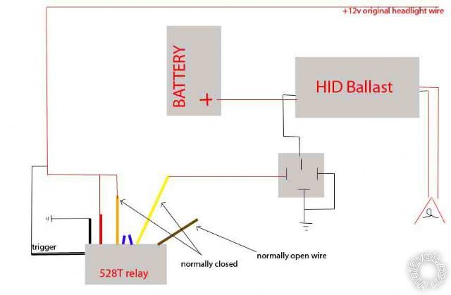
 You just need four connections with this circuit, you'll use it to interrupt the power to the HID lights shown at the green and orange markers, and connect to your starter motor at the pink marker, and ground at the black marker.
The starter motor pulse when you push the start button energizes the upper relay in latching configuration (this can be just a small relay).
When you release the starter, the pink marker immediately becomes a ground, and provides the 12V differential across the coil on the bottom relay to switch it on.
Note it's the bottom relay that needs to be large enough to handle whatever you're switching. I have it controlling all the lighting on the bike, along with the HID headlights.
When you switch off the bike, the power is cut off from the green marker, and the relays open up, and you're back where you started.
I have another modification to it that adds an extra delay after the starter button is released before switching on the headlights, in the event your bike isn't running well enough to start on the first crank. Mine starts on the first crank cycle so I haven't bothered changing it yet.
You just need four connections with this circuit, you'll use it to interrupt the power to the HID lights shown at the green and orange markers, and connect to your starter motor at the pink marker, and ground at the black marker.
The starter motor pulse when you push the start button energizes the upper relay in latching configuration (this can be just a small relay).
When you release the starter, the pink marker immediately becomes a ground, and provides the 12V differential across the coil on the bottom relay to switch it on.
Note it's the bottom relay that needs to be large enough to handle whatever you're switching. I have it controlling all the lighting on the bike, along with the HID headlights.
When you switch off the bike, the power is cut off from the green marker, and the relays open up, and you're back where you started.
I have another modification to it that adds an extra delay after the starter button is released before switching on the headlights, in the event your bike isn't running well enough to start on the first crank. Mine starts on the first crank cycle so I haven't bothered changing it yet.

Posted: January 30, 2010 at 1:28 AM / IP Logged
Posted: January 30, 2010 at 11:53 AM / IP Logged
Posted: February 04, 2010 at 3:47 PM / IP Logged
Posted: February 04, 2010 at 4:43 PM / IP Logged
 Printable version
| You cannot post new topics in this forum You cannot reply to topics in this forum You cannot delete your posts in this forum You cannot edit your posts in this forum You cannot create polls in this forum You cannot vote in polls in this forum |

| Search the12volt.com |
Follow the12volt.com 
Wednesday, May 13, 2026 • Copyright © 1999-2026 the12volt.com, All Rights Reserved • Privacy Policy & Use of Cookies

Wednesday, May 13, 2026 • Copyright © 1999-2026 the12volt.com, All Rights Reserved • Privacy Policy & Use of Cookies
Disclaimer:
*All information on this site ( the12volt.com ) is provided "as is" without any warranty of any kind, either expressed or implied, including but not limited to fitness for a particular use. Any user assumes the entire risk as to the accuracy and use of this information. Please
verify all wire colors and diagrams before applying any information.
