the12volt.com spacer
icon

used car with alarm, 04 tundra, code alarm


Post ReplyPost New Topic
< Prev Topic Next Topic >
lectricguy 
Copper - Posts: 359
Copper spacespace
Joined: March 18, 2008
Location: Rhode Island, United States
Posted: April 25, 2010 at 6:25 PM / IP Logged  

j.w.-

  Great diagram...this will help debug what is happening.   This is what I see:

   1.) Relay on the left side of your diagram is the lock relay--this is hooked up correctly.

    2.) Relay on the right side is your unlock relay, and this wired incorrectly.  Instead of using 2 diodes, the unlock looks like it was hooked up with 1 diode and a relay...not sure why it was done this way, but this setup can be made to work.  Here is what you need to do to correct it. 

                If you trace back the blue and black wires connected to the unlock relay pin 85, I'll bet blue is going to CA425 negative unlock signal (Blue from the Brain's lock/unlock connector).  My guess is black wire is going to ground.  You need to confirm this.   If this is the case, remove ONLY the black (Ground) from pin 85 (leave the Blue unlock signal from the brain on pin 85) and connect the black wire to pin 30.   

You end up with the following connections on your unlock relay:

   Power (+12V) on Pin 86

   Remote Start negative unlock (blue from Brain Lock/Unlock connector) signal on pin 85

   Diode from lock detect and vehicle unlock signal (light green and RED / silver) on Pin 87

   Ground on Pin 30

Lectric Guy
j.w. 
Member - Posts: 42
Member spacespace
Joined: February 02, 2005
Location: United States
Posted: April 25, 2010 at 7:48 PM / IP Logged  
that did it! thanks! i now have 2-stage unlock keyless entry. however, the doors do not lock when i arm the system. could this be an optional setting? I see that i can toggle "Passive Locks" in programming; could this be it? I had to call it a night, but will try changing the setting tomorrow to test it.
thanks again!
lectricguy 
Copper - Posts: 359
Copper spacespace
Joined: March 18, 2008
Location: Rhode Island, United States
Posted: April 25, 2010 at 8:16 PM / IP Logged  

j.w.-

  Active locking or arming requires you to use the transmitter to lock & arm the vehicle.  It should both lock and arm when you press the transmitter lock button.  Passive locking or passive arming will automatically

lock or arm (you can select either or both to be passive) 1 minute after the last door is closed, or if the transmitter lock is pressed.  

  If the doors are not locking  when you press the transmitter, I would check to make sure the lock relay is activating (you can hear the click, or feel the relay while pressing the lock button on the transmitter).  If it is not, make sure the connections to the relay are good (i.e., not loose or initermittent).   The diagram you provided is correct; if the wiring is good, you may have a faulty relay. 

Lectric Guy
j.w. 
Member - Posts: 42
Member spacespace
Joined: February 02, 2005
Location: United States
Posted: April 25, 2010 at 9:00 PM / IP Logged  
gotchya. i will confirm connections and wiring. would this work as a replacement relay?
also, could you recommend the best parts for re-wiring this properly? as of now, the wires are all spliced and connected by twists and electrical tape. I'm sure there is a better way, right? Thanks man. I'm pretty inexperienced with this, but really enjoying learning!
j.w. 
Member - Posts: 42
Member spacespace
Joined: February 02, 2005
Location: United States
Posted: April 25, 2010 at 9:06 PM / IP Logged  
oh, and on another note, the alarm has been going off randomly. I thought it might be the shock sensor, so i disabled it (in programming, decreased the sensitivity one click past the lowest setting). But it happened again. Any idea what this could be?
lectricguy 
Copper - Posts: 359
Copper spacespace
Joined: March 18, 2008
Location: Rhode Island, United States
Posted: April 26, 2010 at 9:09 AM / IP Logged  

1.) The relay you identified will work.  I would make sure all your connections are good first before changing the relay.  If the connections were made poorly, the wiring is more likely the cause of failure or intermittent operation.

2.) There are many opinions on the best method of connection; if any of the methods are not done correctly, they can be problematic.  I prefer soldering the connections, then taping the connection with high quality electrical tape.  Others prefer using crimp connections, and others prefer twisting the wires together, taping and adding a tie wrap over the tape to keep things tight.  They all work if done correctly, but if not done properly, any approach will eventually fail.

3.) As far as the alarm triggering, you should have an LED from the CA425 somewhere in the vehicle that indicates it is armed (note that sometimes this LED is not in an obvious place, but you should be able to trace it from the brain).   When the alarm is triggered and either disarmed by the transmitter or completing the alarm cycle (30 seconds, I believe), the LED flashes a specific number of times indicating what caused the alarm to trigger.   From the CA 425 install manual:

The LED flashes a number of times to indicate which input triggered the alarm:

Number of flashes:

1 - Interior Theft Sensor (Shock Sensor)

2 -Hood/Trunk input

3 - Door Input

Please note the LED clears when you turn the ignition on.  I would check the LED status after the next trigger event to help isolate the problem.

Lectric Guy
j.w. 
Member - Posts: 42
Member spacespace
Joined: February 02, 2005
Location: United States
Posted: April 26, 2010 at 3:43 PM / IP Logged  
The alarm went off again, and i confirmed that it was the shock sensor - single flash. I went back and adjusted the shock sensitivity. I noticed that there were two options under that - "Light Touch" and "Full Trigger" (btw, what's the difference?). I had "light touch" disabled, but "full trigger" was still set to a pretty high sensitivity. I went ahead and disabled that as well. We'll see if that does the trick!
I checked the wiring on the relay, and everything SEEMED to be ok. I will probably go ahead and rewire it, and see if that does the trick. If not, i'll replace the relay. I found this relay at Radio Shack. Will it work? It would save me on shipping cost and transit time if i could pick that up from a nearby "Shack".
lectricguy 
Copper - Posts: 359
Copper spacespace
Joined: March 18, 2008
Location: Rhode Island, United States
Posted: April 26, 2010 at 5:02 PM / IP Logged  

j.w.-

 For the shock sensor, "light touch" is a pre-trigger/warning setting, and will not initiate a full alarm trigger, just warning chirps.  "Full trigger" is the full alarm trigger.

The Radio Shack relay is only SPST(single poll/single throw) with a normally open contact.  The relay you need for the replacement of your lock relay would be SPDT (single pole/ double throw), or SPST with a normally closed contact.  Bottom line-it won't work for your lock relay application.

As a note, I have seen 12V SPDT relays at Pep Boys--in the same display where they have Bulldog Security Remote Starters.  They are listed as 40A relays from A2C, the company that markets Bulldog. 

Lectric Guy
j.w. 
Member - Posts: 42
Member spacespace
Joined: February 02, 2005
Location: United States
Posted: April 26, 2010 at 10:31 PM / IP Logged  
Thanks for the clarification on the sensors.
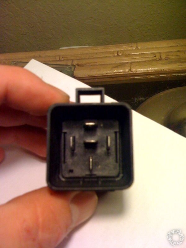
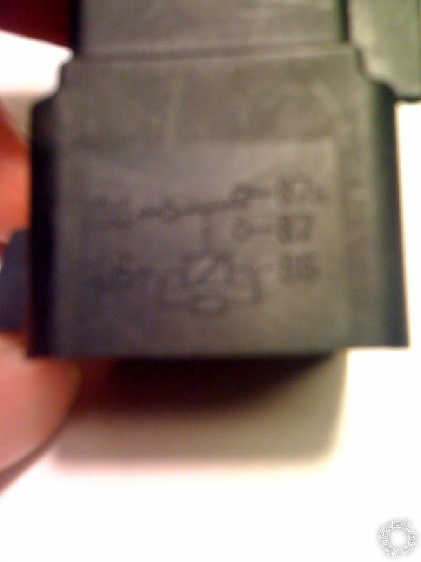
I stopped by Pep Boys and picked up a relay (pics below). I confirmed the connections and then replaced the relay, but still no luck :( What would be my next step?
Thx
used car with alarm, 04 tundra, code alarm - Page 4 -- posted image.
used car with alarm, 04 tundra, code alarm - Page 4 -- posted image.used car with alarm, 04 tundra, code alarm - Page 4 -- posted image.
howie ll 
Pot Metal - Posts: 16,466
Pot Metal spacespace
Joined: January 09, 2007
Location: United Kingdom
Posted: April 27, 2010 at 2:53 AM / IP Logged  
We appear to be running around in circles here guys, some thoughts that may cast light on the problems.
Why 2 relays? I appreciate using the one with diodes as per the Audiovox diagramme but why 2?
I've never used a relay for the locks on a Toyota except the UK IS Lexus where you need to get to the motor wires.
I'll take this a stage further, I did 2 Harriers/Lex RX recently where I went into the driver's door, connected to two wires low current neg at the rear of the door, lock and unlock, extended pulse for comfort close, no relays, no diodes! I've got photos as proof!
Test the locks to see if you can make the locks work you should only need a decent test light, also test the units lock and unlock outputs.
Page of 7

  Printable version Printable version Post ReplyPost New Topic
You cannot post new topics in this forum
You cannot reply to topics in this forum
You cannot delete your posts in this forum
You cannot edit your posts in this forum
You cannot create polls in this forum
You cannot vote in polls in this forum

  •  
Search the12volt.com
Follow the12volt.com Follow the12volt.com on Facebook
Saturday, April 27, 2024 • Copyright © 1999-2024 the12volt.com, All Rights Reserved Privacy Policy & Use of Cookies
Disclaimer: *All information on this site ( the12volt.com ) is provided "as is" without any warranty of any kind, either expressed or implied, including but not limited to fitness for a particular use. Any user assumes the entire risk as to the accuracy and use of this information. Please verify all wire colors and diagrams before applying any information.

Secured by Sectigo
the12volt.com spacer
Support the12volt.com
Top
the12volt.com spacer