the12volt.com spacer
icon

2003 chevy silverado viper 5301 wiring


Post ReplyPost New Topic
< Prev Topic Next Topic >
zerepdivad 
Silver - Posts: 605
Silver spaceThis member has made a donation to the12volt.com. Click here for more info.spacespace
Joined: July 03, 2006
Location: Wisconsin, United States
Posted: December 16, 2010 at 12:18 AM / IP Logged  
to be honest from the looks of that i would just walk away.....
http://www.xpresskit.com/DocumentDownload.aspx?documentid=6027&productid=125&firmwareid=1633
here is the manual for the dlpk it makes it VERY SIMPLE. it's an easy truck. about 4 wires to hook up with d2d(i don't recommend it)
and like 12 hooked up w2w. again not a whole lot because it's mainly from bypass to unit wiring.
tach you should hook up to the white wire at the cluster.
the viper manual will clearly tell you how to program it for automatic mode.
turn key on then off, then hold programming switch, horn will honk, continue holing, horn will honk twice, continue to hold, horn will honk 3 times, then press the button once more and then once again but you hold it this time. you will hear a single horn honk, press lock or unlock on the viper fob until it honks twice.
A DMM is a beautiful thing.
MECP Advanced Installer Certified.
smokeman1 
Platinum - Posts: 1,588
Platinum spaceThis member has made a donation to the12volt.com. Click here for more info.spaceThis member has been recognized as an authority in Mobile Security and Convenience. Click here for more info.spacespace
Joined: September 14, 2009
Location: Wisconsin, United States
Posted: December 16, 2010 at 7:14 AM / IP Logged  

Have you tested and verified with a DMM that both of the RED wires at the ignition harness are 12 volts constant?

In D2D Mode of the DLPKGM instructions, I don't see a connection for Lt. Green and Blue.  Only in W2W Mode.

Wire Guide from AudioVox:   Only one RED listed for 12 volts constant, so test those RED wires at Ignition.  Brown is listed as Accessory 2. But you need to test and verify with a DMM.

Follow the previous post for getting the unit into AUTO Mode.

Battery RED (+) IGNITION SWITCH HARNESS
2003 chevy silverado viper 5301 wiring - Page 2 -- posted image. Ignition 1 PINK (+) IGNITION SWITCH HARNESS
2003 chevy silverado viper 5301 wiring - Page 2 -- posted image. Ignition 2 WHITE (+) IGNITION SWITCH HARNESS
2003 chevy silverado viper 5301 wiring - Page 2 -- posted image. Accessory 1 ORANGE (+) IGNITION SWITCH HARNESS
2003 chevy silverado viper 5301 wiring - Page 2 -- posted image. Accessory 2 BROWN (+) IGNITION SWITCH HARNESS
2003 chevy silverado viper 5301 wiring - Page 2 -- posted image. Starter 1 YELLOW (+) IGNITION SWITCH HARNESS
2003 chevy silverado viper 5301 wiring - Page 2 -- posted image. Anti-Theft Type PASSLOCK II
2003 chevy silverado viper 5301 wiring - Page 2 -- posted image. Anti-Theft Descript A RESISTANCE BASED SYSTEM
2003 chevy silverado viper 5301 wiring - Page 2 -- posted image. Key Sense LIGHT GREEN (-) AT STEERING COLUMN HARNESS
2003 chevy silverado viper 5301 wiring - Page 2 -- posted image. Tachometer WHITE (-) AT INSTRUMENT CLUSTER 2003 chevy silverado viper 5301 wiring - Page 2 -- posted image.
2003 chevy silverado viper 5301 wiring - Page 2 -- posted image. Speed Sense DARK GREEN / WHITE (AC) IN RADIO HARNESS 2003 chevy silverado viper 5301 wiring - Page 2 -- posted image.
2003 chevy silverado viper 5301 wiring - Page 2 -- posted image. Parking Lights BROWN (+) DRIVERS KICK PANEL
2003 chevy silverado viper 5301 wiring - Page 2 -- posted image. Low Crr. Pk Lights GRAY/BLACK (-) AT LIGHT SWITCH OR BROWN PLUG AT BCM PIN B2
2003 chevy silverado viper 5301 wiring - Page 2 -- posted image. Brake Lights WHITE (+) AT BRAKE PEDAL SWITCH
2003 chevy silverado viper 5301 wiring - Page 2 -- posted image. Reverse Lights LIGHT GREEN (+) BCM BLACK PLUG PIN F
2003 chevy silverado viper 5301 wiring - Page 2 -- posted image. Horn BLACK OR BLACK / YELLOW (-) AT STEERING COLUMN HARNESS

When all else fails, Read the Instructions
Support the12volt.com Make a Donation
ericsigman 
Member - Posts: 13
Member spacespace
Joined: December 12, 2010
Posted: December 16, 2010 at 9:00 AM / IP Logged  

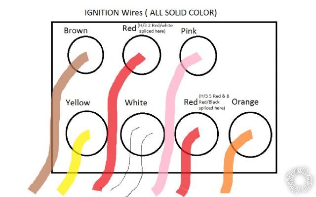
Below is what my IGN harness looks like. You can see it in my pictures but here is a drawing with a few notes. There are definately 7 wires here ( not 6 like above)

2003 chevy silverado viper 5301 wiring - Page 2 -- posted image.

ericsigman 
Member - Posts: 13
Member spacespace
Joined: December 12, 2010
Posted: December 16, 2010 at 10:00 AM / IP Logged  

Another problem is i have no NORN honk. I dont think i hooked this up - do i need it or does it just make it easier to program?

I will hook the Tach to the white wire at the cluster when i get home ( except it it snowing right now)

Any thoughts on which RED @ IGN i should be using? i guess on i wrong.

smokeman1 
Platinum - Posts: 1,588
Platinum spaceThis member has made a donation to the12volt.com. Click here for more info.spaceThis member has been recognized as an authority in Mobile Security and Convenience. Click here for more info.spacespace
Joined: September 14, 2009
Location: Wisconsin, United States
Posted: December 16, 2010 at 12:10 PM / IP Logged  

The only way to know for sure what the RED wires are is to test them with a DMM.  The 12 volts constant should have 12 volts on the wire all the time. Just because the is a RED wire there does not mean it is a correct wire.

Go to the download section of this site and download the Viper 5701 INSTALL Guide/Manual.    Starting on page 13 is a section on locating the wires you need.  You need to use a DMM, it is the only way to know what you are connecting to on the vehicle.  The wiring guide are not always correct.

Having the horn connected will help in knowing which menu you are in and which feature/option.  It take a bit of timing, practice, and cooridinated button pressing.

When all else fails, Read the Instructions
Support the12volt.com Make a Donation
ericsigman 
Member - Posts: 13
Member spacespace
Joined: December 12, 2010
Posted: December 16, 2010 at 12:54 PM / IP Logged  
Thanks smokeman1. I'll check it when i get home. what setting am i using with the DMM?
smokeman1 
Platinum - Posts: 1,588
Platinum spaceThis member has made a donation to the12volt.com. Click here for more info.spaceThis member has been recognized as an authority in Mobile Security and Convenience. Click here for more info.spacespace
Joined: September 14, 2009
Location: Wisconsin, United States
Posted: December 16, 2010 at 4:33 PM / IP Logged  

Set it on the DC side.  20 if it is on the scale.

When all else fails, Read the Instructions
Support the12volt.com Make a Donation
ericsigman 
Member - Posts: 13
Member spacespace
Joined: December 12, 2010
Posted: December 16, 2010 at 5:05 PM / IP Logged  

I cant walk away now...i thought this has gone pretty smooth refering to the actual install.

So your saying, from looking at my wires post above, all i need to hook up is my TACH wire? Should i hook up tach behind dash cluster or through engine bay. Also, why is the lock and unlock on the remote not working, im just getting the dash and headlights to flash?

My horn wire is NOT hooked up so when trying to program, i get nothing but the blue light flashing. Do i need the horn hooked up and if i do, what wire is it on the steering column? Left or right side?

Thanks for the help guys...I think im close but i just need to be walked through it.

ericsigman 
Member - Posts: 13
Member spacespace
Joined: December 12, 2010
Posted: December 16, 2010 at 6:11 PM / IP Logged  
well...I tested both RED wires at the IGN with the key off and they b oth registered 12.4?
ericsigman 
Member - Posts: 13
Member spacespace
Joined: December 12, 2010
Posted: December 16, 2010 at 7:28 PM / IP Logged  

OK guys.... I got everything to WORK!

The biggest thing was hooking up the H/1 3 Brown horn wire to the Black BCM pin 9 wire(grey pug). This let me hear the programing honks.

The truck locks and unlocks, and the remote start works.

Thanks for all the help. I'm not in the clear yet, still have to solder everything and make it look stock again ( this should be fun)

I'll keep you posted and again THANKS.

Page of 2

Sorry, you can NOT post a reply.
This topic is closed.

  Printable version Printable version Post ReplyPost New Topic
You cannot post new topics in this forum
You cannot reply to topics in this forum
You cannot delete your posts in this forum
You cannot edit your posts in this forum
You cannot create polls in this forum
You cannot vote in polls in this forum

  •  
Search the12volt.com
Follow the12volt.com Follow the12volt.com on Facebook
Friday, April 19, 2024 • Copyright © 1999-2024 the12volt.com, All Rights Reserved Privacy Policy & Use of Cookies
Disclaimer: *All information on this site ( the12volt.com ) is provided "as is" without any warranty of any kind, either expressed or implied, including but not limited to fitness for a particular use. Any user assumes the entire risk as to the accuracy and use of this information. Please verify all wire colors and diagrams before applying any information.

Secured by Sectigo
the12volt.com spacer
Support the12volt.com
Top
the12volt.com spacer