the12volt.com spacer
icon

2 3 seconds to trigger relay


Post ReplyPost New Topic
< Prev Topic Next Topic >
cmorales 
Member - Posts: 16
Member spacespace
Joined: July 15, 2004
Location: Mexico
Posted: January 12, 2011 at 3:05 PM / IP Logged  
I been searching for a way to trigger a relay ONLY if I press a switch longer than 2 or 3 seconds and only thing I could find is this old tread.
Will this work or is there a better simpler way?
Thanks.
i am an idiot 
Platinum - Posts: 13,666
Platinum spaceThis member consistently provides reliable informationspace
Joined: September 21, 2006
Location: Louisiana, United States
Posted: January 12, 2011 at 8:43 PM / IP Logged  
That is pretty much a failsafe way to do it.
cmorales 
Member - Posts: 16
Member spacespace
Joined: July 15, 2004
Location: Mexico
Posted: January 13, 2011 at 9:41 AM / IP Logged  
Thanks.
I´m trying to prevent opening the trunk by mistake, the switch is too accesible...
Can I put two 4700uF capacitors in series to get 9400uF?
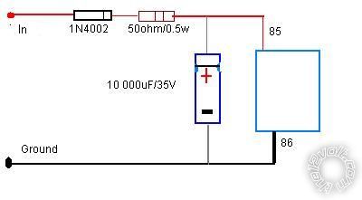
2 3 seconds to trigger relay -- posted image.
cmorales 
Member - Posts: 16
Member spacespace
Joined: July 15, 2004
Location: Mexico
Posted: January 13, 2011 at 9:48 AM / IP Logged  
Found it... the capacitors need to be in parallel to add capacitances.
Thanks
cmorales 
Member - Posts: 16
Member spacespace
Joined: July 15, 2004
Location: Mexico
Posted: January 13, 2011 at 10:17 PM / IP Logged  
Well. It didn't worked. Could it be because I used two 4700 uM capacitors in parallel?
i am an idiot 
Platinum - Posts: 13,666
Platinum spaceThis member consistently provides reliable informationspace
Joined: September 21, 2006
Location: Louisiana, United States
Posted: January 14, 2011 at 10:05 AM / IP Logged  
The only thing that would keep this from working is the direction of or the placement of the diode.  The drawing has the diode in the positive leg.  If the diode is in the negative leg, you must turn it around.
cmorales 
Member - Posts: 16
Member spacespace
Joined: July 15, 2004
Location: Mexico
Posted: January 14, 2011 at 11:00 AM / IP Logged  
connected everything as the diagram. only thing different is the capacitor, I used two 4700uF/25v capacitors in parallel. The thing was that the relay activated instantly and not after 2 secs.
cmorales 
Member - Posts: 16
Member spacespace
Joined: July 15, 2004
Location: Mexico
Posted: January 14, 2011 at 11:23 AM / IP Logged  
Here´s a better description of what I´m trying to solve...
...In my car (12v, negative earth) I have a boot opening switch (momentary) that opens the boot by triggering a solenoid. All well and good but they situated it right next to the power windows. The number of times I have just brushed it whilst opening the window is getting beyond a joke and quite embarrassing at traffic lights.
What I would like to do is to have to hold the switch down for 2 or 3 seconds before it passes the voltage to the existing relay that feeds the boot solenoid. If the switch is pressed and released then the timer is reset (obviously don't want accidental presses building up)...
Thanks
cmorales 
Member - Posts: 16
Member spacespace
Joined: July 15, 2004
Location: Mexico
Posted: January 14, 2011 at 1:51 PM / IP Logged  
What if put the resistor between the capacitor and the relay?
The relay is a 12v/30A automotive relay. Does that makes a difference?
i am an idiot 
Platinum - Posts: 13,666
Platinum spaceThis member consistently provides reliable informationspace
Joined: September 21, 2006
Location: Louisiana, United States
Posted: January 14, 2011 at 8:40 PM / IP Logged  
The resistor has to be exactly where it is in the diagram.  Are you sure you have a 50 ohm resistor, and 4700 mic capacitors. 
Page of 2

  Printable version Printable version Post ReplyPost New Topic
You cannot post new topics in this forum
You cannot reply to topics in this forum
You cannot delete your posts in this forum
You cannot edit your posts in this forum
You cannot create polls in this forum
You cannot vote in polls in this forum

  •  
Search the12volt.com
Follow the12volt.com Follow the12volt.com on Facebook
Thursday, March 28, 2024 • Copyright © 1999-2024 the12volt.com, All Rights Reserved Privacy Policy & Use of Cookies
Disclaimer: *All information on this site ( the12volt.com ) is provided "as is" without any warranty of any kind, either expressed or implied, including but not limited to fitness for a particular use. Any user assumes the entire risk as to the accuracy and use of this information. Please verify all wire colors and diagrams before applying any information.

Secured by Sectigo
the12volt.com spacer
Support the12volt.com
Top
the12volt.com spacer