the12volt.com spacer
icon

viper 5901, 2004 ford ranger


Post ReplyPost New Topic
< Prev Topic Next Topic >
chaddaddy 
Copper - Posts: 55
Copper spacespace
Joined: January 21, 2011
Posted: January 21, 2011 at 11:45 AM / IP Logged  
I just bought a viper 5901 and im installing it on a 2004 Ford ranger 5 speed. My question is first, what wires do i connect to 12V constant? Can I just run these straight to the battery? Also the I have the green, purple, orange, and pink wires all done that was pretty easy but Im very confused about all the rest of them? any input is greatly appreciated
chaddaddy 
Copper - Posts: 55
Copper spacespace
Joined: January 21, 2011
Posted: January 21, 2011 at 11:51 AM / IP Logged  
Also I got a harness that has 18 wires on it. What is this one for I dont see it in the instal manual???
t&t tech 
Platinum - Posts: 2,608
Platinum spacespace
Joined: October 05, 2008
Location: Trinidad and Tobago
Posted: January 21, 2011 at 7:09 PM / IP Logged  

List your wire s and we'll tell you what to do! All the heavy reds can connect to the 12 constant at the ignition harness,

PINK- IGNITION

ORANGE- ACCESSORY

PINK/WHITE- 1ST IGNITION

GREEN- STRTER KEY SIDE

PURPLE - STARTER ENGINE SIDE

PINK/BLACK- CUT AND ISOLATE.

kreg357 
Platinum - Posts: 7,783
Platinum spaceThis member has made a donation to the12volt.com. Click here for more info.spaceThis member has been recognized as an authority in Electrical Theory. Click here for more info.spaceThis member has been recognized as an authority in Mobile Security and Convenience. Click here for more info.spacespace
Joined: January 30, 2009
Location: Pennsylvania, United States
Posted: January 21, 2011 at 8:26 PM / IP Logged  

Looks like you have the new and improved Viper 5901.  They moved some wires around on you.  The 18 Pin harness is H2.  Here is a pin-out.

H2/1- LHT GRN/BLK (-) 200mA OEM ALARM DISARM OUTPUT

H2/2- ORG/BLK (-) 200mA AUX 4 OUTPUT
H2/3- GRN/WHT (-) 200mA OEM ALARM ARM OUTPUT
H2/4- VIOL/BLK (-) 200mA AUX 2 OUTPUT
H2/5- WHT/BLK (-) 200mA AUX 3 OUTPUT
H2/6- WHT/VIOL (-) 200mA AUX 1 OUTPUT
H2/7- GRY/BLK (-) 200mA DIESEL WAIT TO START
H2/8- BRW/BLK (-) 200mA HORN HONK OUTPUT
H2/9- VIOL/WHT TACHOMETER INPUT
H2/10- DRK BLU (-) 200mA STATUS OUTPUT
H2/11- PINK/WHT (-) 200mA FLEX RELAY CONTROL OUTPUT
H2/12- ORG (-) 200mA ACC OUTPUT
H2/13- PRPL (-) 200mA STARTER OUTPUT
H2/14- PINK (-) 200mA IGNITION 1 OUTPUT
H2/15- GRY (-) 200mA HOOD PIN INPUT (N/C N/O)
H2/16- BLU/WHT (-) 200mA 2ND STATUS/REAR DEFFOGER OUTPUT
H2/17- BRW (+) BRAKE SHUTDOWN INPUT
H2/18- BLK/WHT (-) NEUTRAL SAFETY INPUT

Soldering is fun!
chaddaddy 
Copper - Posts: 55
Copper spacespace
Joined: January 21, 2011
Posted: January 21, 2011 at 10:37 PM / IP Logged  
Ok cool thanks man. So I dont have to use the RED wire then? Just the ink and white? And whats the difference between Ignition 1 and 2?
Also with the 18 wire harness. I hate to be a pest but can you explain what those are for, where they go, and which ones ARE ABSOLUTELY NECESSARY!
Thanks a bunch for the input.
dragonpntr 
Member - Posts: 15
Member spacespace
Joined: January 04, 2011
Location: Nebraska, United States
Posted: January 21, 2011 at 11:22 PM / IP Logged  

H2/1- LHT GRN/BLK (-) 200mA OEM ALARM DISARM OUTPUT /   Goes to GREEN/ purple in driver door boot  -

H2/10- DRK BLU (-) 200mA STATUS OUTPUT                /                 To ground when running on security module
H2/17- BRW (+) BRAKE SHUTDOWN INPUT                    /                 Lt. Green at brake pedal  +
H2/18- BLK/WHT (-) NEUTRAL SAFETY INPUT                 /                 Ground

Red, RED / white, and RED / black if you have it go to the large yellow wires at the ignition switch

Clutch bypass is pink at the switch and is +

You do not need the disarm wire if the truck does not have power locks or factory alarm. You can check for the alarm by locking the door while open with the switch then closing it. Wait about 5 min. then open the door without using the key if the horn honks it has an alarm.

chaddaddy 
Copper - Posts: 55
Copper spacespace
Joined: January 21, 2011
Posted: January 22, 2011 at 12:33 AM / IP Logged  
Ok then the truck didn't come with power locks, windows, or an alarm. It has an anti theft system though. So is H2/1 needed and if so where do i connect it? What about H1/3?
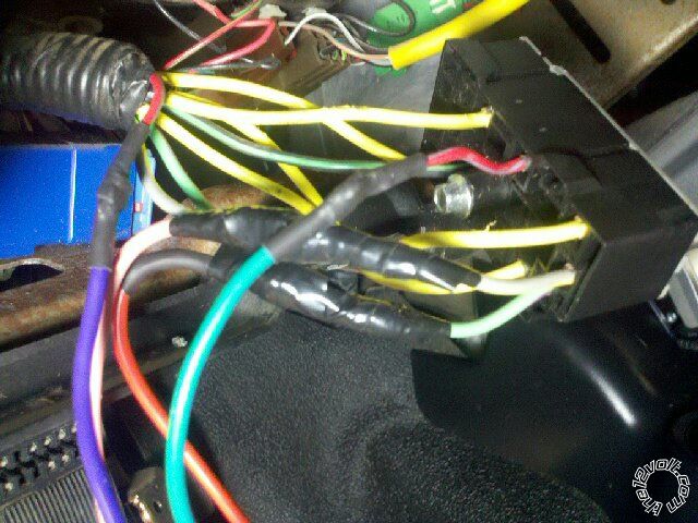
With the Red, RED / white, and RED / black let me ask you this. Look at the picture below. What yellow wire.....theres four... hahah. viper 5901, 2004 ford ranger -- posted image.
dragonpntr 
Member - Posts: 15
Member spacespace
Joined: January 04, 2011
Location: Nebraska, United States
Posted: January 22, 2011 at 2:16 AM / IP Logged  

There is 4 of them they all are constant hook up your 3 constant powers to 3 of them also your large pink/white should go to the gray / YELLOW and change it in the programing to an acc.

pink to GREEN/ purple

orange to BLACK/ green

red to 1 yellow

RED / white to 1 yellow

RED / black to 1 yellow

You won't need H 2/1

To do the immobilizer you will need a security module or if you don't mind losing a key you could make a bypass here is a link to a document.    https://www.the12volt.com/installbay/file.asp?ID=610

chaddaddy 
Copper - Posts: 55
Copper spacespace
Joined: January 21, 2011
Posted: January 22, 2011 at 3:31 AM / IP Logged  
Alright cool thanks man. So the following ones Im having trouble with : H2/2,34,5,6,9,10,11,12,13,14,16 I just need to know what there for and where they hook up to if they can be hooked up at all.
Thaks for all your help im slowly getting this thing finished :)
chaddaddy 
Copper - Posts: 55
Copper spacespace
Joined: January 21, 2011
Posted: January 22, 2011 at 4:34 AM / IP Logged  
Also, I am hooking up the clutch bypass and the ebake right now.... im lost... what wires do i use and how do i connect them?
Page of 5

  Printable version Printable version Post ReplyPost New Topic
You cannot post new topics in this forum
You cannot reply to topics in this forum
You cannot delete your posts in this forum
You cannot edit your posts in this forum
You cannot create polls in this forum
You cannot vote in polls in this forum

  •  
Search the12volt.com
Follow the12volt.com Follow the12volt.com on Facebook
Wednesday, April 24, 2024 • Copyright © 1999-2024 the12volt.com, All Rights Reserved Privacy Policy & Use of Cookies
Disclaimer: *All information on this site ( the12volt.com ) is provided "as is" without any warranty of any kind, either expressed or implied, including but not limited to fitness for a particular use. Any user assumes the entire risk as to the accuracy and use of this information. Please verify all wire colors and diagrams before applying any information.

Secured by Sectigo
the12volt.com spacer
Support the12volt.com
Top
the12volt.com spacer