the12volt.com spacer
icon

Viper 350, 530t, 2009 Dacia Logan


Post ReplyPost New Topic
< Prev Topic Next Topic >
cristu 
Copper - Posts: 65
Copper spacespace
Joined: March 14, 2011
Location: Romania
Posted: March 19, 2011 at 12:51 PM / IP Logged  
I need to connect an 12V / 20mA electroliminiscet led to my car.
When I stop the engine the led starts to blink and when I ran the engine the led stops. Can you provide an diagram how to connectit to my car ? Do I need to use an relay ? Can you make me the connections to my relay. Thank you.
oldspark 
Gold - Posts: 4,913
Gold spacespace
Joined: November 03, 2008
Location: Australia
Posted: March 19, 2011 at 7:06 PM / IP Logged  
I presume you mean you have a 12V 20mA flashing LED.
Connect the +ve end to battery +12V and the -ve end to IGN +12V.
There is no need for a relay (the relay will consume more power than the LED).
cristu 
Copper - Posts: 65
Copper spacespace
Joined: March 14, 2011
Location: Romania
Posted: March 20, 2011 at 1:28 AM / IP Logged  
Yes it;s correct it's flashing LED.
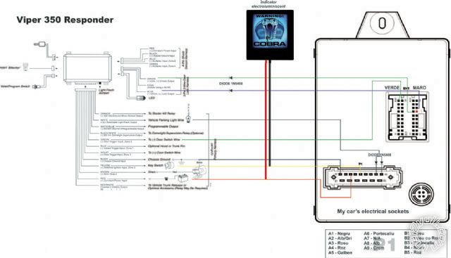
I want to integrate to my car's alarm (when I will mount it). It's Viper 350 Reponder alarm. I attached an diagram with the led connected.
It is correct how I made it ? Shoud I integrate an relay with the alarm ?
Thanks
Viper 350, 530t, 2009 Dacia Logan -- posted image.
howie ll 
Pot Metal - Posts: 16,466
Pot Metal spacespace
Joined: January 09, 2007
Location: United Kingdom
Posted: March 20, 2011 at 2:22 AM / IP Logged  
I can't clearly see your diagram but wire the red wire of the electroluminescent panel to your red 12V+ power wire of the alarm and the black to the alarm's orange GWA wire.
No relay needed because:
a) It will be drawing more power than the alarm ( x about 4).
b) It will flatten your battery during the time the alarm is armed.
cristu 
Copper - Posts: 65
Copper spacespace
Joined: March 14, 2011
Location: Romania
Posted: March 20, 2011 at 8:17 AM / IP Logged  
Hi Howie
You mean H1/1 ORANGE (-) ground-when-armed output ?
From the alarm's manual: >> This wire supplies a (-) ground as long as the system is armed. This output ceases as soon as the system is disarmed. The orange wire is pre-wired to control the 8618 starter kill relay. It can supply up to 500 mA of current.
NOTE: If using the H1/1 Orange wire to activate an add-on accessory such
as window automation, or voice module a 1Amp diode must be installed to
ensure proper operation.
Should I install a diode on this wire (orange) or leave it just simple ?
Thanks
howie ll 
Pot Metal - Posts: 16,466
Pot Metal spacespace
Joined: January 09, 2007
Location: United Kingdom
Posted: March 20, 2011 at 8:43 AM / IP Logged  
Yes to the first question.
You will only need a diode if the GWA is powering other devices such as a window closer.
A diode (1N4004) in-line for each branch, towards the alarm.band or cathode
cristu 
Copper - Posts: 65
Copper spacespace
Joined: March 14, 2011
Location: Romania
Posted: March 21, 2011 at 6:18 AM / IP Logged  
Hello
I want to connect an alarm system to my car and I want to do it myself. I have the diagram's alarm and I know where is the sockets/harness at my car.
I'm a novice regarding the electrical wires from a car so I want to identify and test the wires before soldering and other joins to do.
I have identified the red constant power input wire with a digital multimeter, the ground wire, the (+) after contact - key switch (yellow wire) but how can I identify and test the other wires (car's side): lock output (-), unlock output (-), door switch wire (-), vehicle parking light wire etc.
Can you tell me how to identify these wires with an multimeter ? or can I simulate the lock/unlock the doors with the multimeter or test light. Is there any tutorials or documentations regarding this matter
Thanks
heinstal 
Member - Posts: 34
Member spacespace
Joined: October 09, 2008
Location: Ontario, Canada
Posted: March 21, 2011 at 7:37 AM / IP Logged  

well cristu it depends on the car actually. Most of the time those wires can be found on the BCM or some juncion connector under the dash. once you have the car model look it up on this site under vehicle wiring at the top of the page. the door lock and unlock are usually negative triggered so you will see a 12 V voltage when using a multimeter and when the door lock is pushed it will go to 0.

BUT before testing wires look up their location on the site!

~~~wael~~~
cristu 
Copper - Posts: 65
Copper spacespace
Joined: March 14, 2011
Location: Romania
Posted: March 22, 2011 at 10:54 AM / IP Logged  
Hi I make the scheme of Viper 350 Responder with the coonections to my car. Can You tell me if I connect the diodes correctly to wires ? and if the wires are ok ?
Thanks
Viper 350 Responder diagram
ftp://86.121.93.92:2020/Viper_350.pdf
howie ll 
Pot Metal - Posts: 16,466
Pot Metal spacespace
Joined: January 09, 2007
Location: United Kingdom
Posted: March 22, 2011 at 3:54 PM / IP Logged  
What car? Make model and year please.
Page of 11

  Printable version Printable version Post ReplyPost New Topic
You cannot post new topics in this forum
You cannot reply to topics in this forum
You cannot delete your posts in this forum
You cannot edit your posts in this forum
You cannot create polls in this forum
You cannot vote in polls in this forum

  •  
Search the12volt.com
Follow the12volt.com Follow the12volt.com on Facebook
Friday, April 19, 2024 • Copyright © 1999-2024 the12volt.com, All Rights Reserved Privacy Policy & Use of Cookies
Disclaimer: *All information on this site ( the12volt.com ) is provided "as is" without any warranty of any kind, either expressed or implied, including but not limited to fitness for a particular use. Any user assumes the entire risk as to the accuracy and use of this information. Please verify all wire colors and diagrams before applying any information.

Secured by Sectigo
the12volt.com spacer
Support the12volt.com
Top
the12volt.com spacer