With thanks to
syl20rochon - at last! - my
style of diagram.
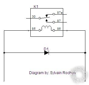
And I'll probably use that in the future (assuming that is ok) though I might add a + & - to show the major point that the Kathode (line) end goes towards +ve. [Otherwise the diode is
forward biased hence effectively a short between + & - and hence blowing the control circuit or fuse or the diode!]
IMO it's a great diagram. It even "aligns" the main contacts to show that 87a is "normally" connected (hence its
NC label/designation where Normally means as if it's
on the shelf - ie, de-energised - as opposed to whatever its
normal operating position might be...
And it shows that the
switch arm goes to the NO Normally Open #87 contact when the coil is
energised thereby
pulling the arm
in towards the coil.
Those
conventions seem to be common and what I endeavor to do in circuit diagrams, though for layout reasons that may not always be followed (ie, Reader: always beware!). But I always show relays in their de-energised state (ie, "Normal") EXCEPT when explaining how a circuit works whereby I might show it in its energised/closed position to clarify power flow...
The actual relay-coil ends are really irrelevant but #86 is the more +ve by convention - that convention being for relays with inbuilt diodes. (Cathode is always #86.)
I don't use inbuilt-diode relays hence I don't worry about the convention in practice... I prefer external diodes so that I can easily replace them, and also "swap" ends if that better suits my layout.
But I stick to #86 +ve & #85 -ve in diagrams IF I include those labels. (That has only happened since joining this forum!) My diagrams are circuit or schematic diagrams for easier
operational understanding by readers, and they can use their relay of choice. (EG - I tend to use Jap JIDECO and others that do not have those DIN labels. Whereas this (and most) forums/sources tend to use Hella/Bosch types, AND show
physical diagrams to assist wiring installation etc.)
Ikessky - the 1N5406 is fine. Yes it's big, but a (power) diode is a power diode - usually only its current capability is the critical factor.
And for spike suppression - usually a voltage of or above 200V, but 400V (IN4004) is the commonly available
lowest voltage power diode. [And a bit of extra margin; 12V coil spikes are often ~100V and sometimes around 200V, hence 400V or higher is chosen. FYI - that's the
breakdown voltage aka PIV of the diode which means (eg) above +400V at the Kathode end overcomes the diode's reverse blocking voltage capability (aka breakdown voltage), hence letting through current, and possibly or probably damaging the diode. PIV is
Peak Inverse Voltage.]
The 1N5406 600V/3A diode exceeds the usually recommended 400V/1A diode. It will handle an extra 200V and 2A - not that current should be an issue (1A is enough), though it does imply more electrical ruggedness. (You can quench a 600V 3A spike, so the expected <200V <1A is no problem. But other things apply too - like construction - eg, because its bigger it may have more flexing/vibration (probably irrelevant); or maybe different internals that aren't as physically strong.)
But use the 1N5406 etc. It's free, or cheap, or available.
And yes, I have blabbed again, but hopefully provided more understanding (else shown my misunderstanding!!), and enabled you to remedy problems more easily - eg, in the very unlikely event that the
bigger & better 1N5406 seems to continually break...
Geez - that was almost Diodes-101 and Diodes-102! (Or Diodes-201?)
Professor Rambles over & out. (Over & Out for this reply only...)
PS FYI - I write
Kathode to
match the diode's circuit symbol and the band/line on the diode itself. The arrow-head in the
K shows the direction of current flow, the upright
| in K and line/band on the diode being the "brick wall" end that blocks current should it try to come in that way. When looking at a real diode, picture the K and IMO you easily remember which way current flows.)


 Printable version


