


oldspark battery bank w/possible solar
Home /
the12volt's Install Bay /
General Discussion / oldspark battery bank w/possible solar ( Topic Closed)
Welcome Guest :)


Posted: September 19, 2011 at 8:38 PM / IP Logged
I get what you're saying about what is practical vs what could be done but considering the field I want to get into this would give me something to do other than some theoretical textbook problem. I know for now I have to make more rudimentary plans for maintenance and the like but down the road I would like to add this system in.
What do you mean by lawsuits?
As for the alternator, it will be used as is for the time being but eventually I plan on modifying it so that the voltage is not limited and the output is fed through a circuit similar to the MPPT solar chargers like you mentioned. The idea would be to measure the power out and rate of discharge to know each batteries state of charge. Then have that circuit figure the required power to charge the batteries, run the generator at it's most efficient point for that power requirement, and then convert it to the appropriate voltage and current combination for the batteries.


Posted: September 19, 2011 at 9:56 PM / IP Logged
Law suits - as in "that oldFart told me solar couldn't power my aircon so I've been melting ever since...." etc.
Like if my bro were to say I said "not for cranking" so he bought a "proper" battery which didn't/won't last as long as the one I said was unsuitable.
I did not mean it seriously, and suits like that would not succeed here (Australia) provided the info was with best intent and not provided negligently. Besides, this and other forums are "no responsibility" (aka "we don't care but have no responsibility anyway..." (LOL!!!), but I know that is not enough to protect anyone - even here (Australia).
I'm with you for down the road adding of self-developed systems etc. But I'm already a few decades behind...
The alternator is a good battery charging source. It's my starting point for cheap water or wind power. It may be far from efficient, but it gets at least some power from scrap- or sparts-bins else cheap sources.
Later comes the improvements as does MPPT once you have the original solar panels required and then realise MPPT is a cost or space saver compared to adding more (required) panels. That's analogous to me replacing my $145 cooler with a $1400 fridge (eBay'd for $900) - that saved money - not to mention other improvements like space, weight, batteries, and colling to -19°C in +45°C ambients instead of ambient minus 20°C). To have bought another 100W of solar would have been false economy even if the sun was reliable.
And thanks - MPPT - I couldn't recall the name. (I am still recovering my PC data.)
But an MPPT is essentially an SMPS (Switched Mode Power Supply) with a method of programming the input voltage (eg, a look up table or means of determining the solar panel output voltage-current for max power) and converting that DC voltage to the DC voltage required (eg, 14.4V for charging batteries, or 13.8V to float batteries etc).
That's a marriage of common & cheap chips ($2-$5 SMPS chips from phone & PC chargers etc, and $5-$20 PICs/PICAXEs) plus associated dc-dc converter components and (PIC) programming. FYI - the cheapest kit I knew of was from OatleyElectronics (12/24V-15A; now AUD$89) though I have seen cheap MPPTs on eBay etc. And I reckon most could be modified for higher currents (upgrade the conversion inductor/coil, beef up the PCB tracks and maybe $3 switching FETs).
BTW - I have other Oatley kits - their dual-battery adapter (aka (smart/voltage-sensing) battery isolator, solar regulator, SLA battery charger booster (versatile dc-dc converter) and components ($3 120A MOSFETs, 80A latching relay, etc).
Yes meltmanbob, I think we have much in common.
My DIY could be described as self-reliance and independence from commercial entities. Usually also far cheaper - even in times of fiscal comfort. (And ironically - in retrospect - far superior!)
But whether a break-down occurs on a suburban street or in the outback days from anywhere and surrounded by dingoes, I want a fix without waiting for emergency road crews or mail or helicopter drops or teeth marks.
Hence my redundant and common-part solutions that are "simple" (though that simplicity can involve EMP-sensitive electronics). [ And hence duplication like wind or gas-engined alternator to be the same as my vehicle alternator, or standard SPDT relays for spares, or building blocks using commonly available accessories. ]
And knowing the emergency fallbacks - like raw solar panels feeding a battery using me as a PWM (manually connecting & disconnecting the +ve wire) or removing the headlight etc to use as a series resistance, and checking for bubbles or heat in lieu of an operational voltmeter. (Someone recently wrote "sticks and stones" but unfortunately not in THIS context LOL!)
Posted: March 09, 2012 at 3:27 AM / IP Logged
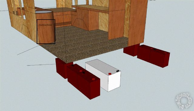
Hey long time! I have a few questions about how to set up the battery bank. To recap, I have 6 Trojan T-1275's rated for 150AH @C20. Right now I am trying to decide the best way to wire them up, so far I've come up with 2 banks of 3, one on each side of the van as near the center as possible side to side and preferably slightly forward of center front to back. I want the 2 banks so that I can wire them to 24v for stick welding. I'm envisioning a small electrical panel near the rear of the side doors where each batteries terminal wires will terminate. One each of the positive and negative distribution blocks will have 2 1/0 gauge outputs along with the 3 4 gauge inputs. The other 2 distribution blocks will only have a single 1/0 out. Each of the 1/0 output wires will have welding connectors rated for 200+ amps. The single 1/0 positive and negative outputs will have paired connectors for series connection.
There will be another set of distribution blocks to tie all of the 12v stuff to. Each positive and negative 12v distribution block will have 2 1/0 wires with welding connectors. When hooked up for 12v, each banks positive and negative connectors are hooked to their 12v spots. For 24v, all power connectors will be removed from the 12v blocks first, then the series connection made and then welding cables connected to the remaining outputs.
My confusion comes in with hooking in the starting battery. I know that when I weld I need to have the battery bank completely isolated from everything else but I still want to have some power available which I'm assuming can come from the starting battery. Now I could have it connected to the 12v blocks which would be the only thing left connected when welding but I'm concerned about problems when starting the van. As far as I understand it, when cranking the vehicle cuts all of the electrical from the battery, is this correct?
I'm hoping that I can just connect the starting battery to the 12v blocks and be done with that part. My theory is that if I'm starting the van, I'm not welding which means that when cranking and the starting battery is cut out, I still have the bank hooked up. If I'm welding then at least the starting battery is still there.
If I do it this way, do I need to worry about surges or power spikes damaging something like my computer running off of an inverter? I'm worried about the sudden disconnecting and reconnecting of the starting battery when starting the van. I'm also worried about the same thing when manually switching the bank from 12 to 24v.
On a side note, my plan was to use 8 gauge wire from the batteries to the bank blocks, 1/0 from the bank blocks to the 12v blocks, 1/0 for the 24v leads and welding cables, 8 gauge from the 12v block to the starting battery (possibly 4ga), 4ga from the bank to the generator.
Welding will be 150a or less, that means no more than 50a max per battery. I know 8 ga isn't the best for voltage drop, roughly .5v @15' @50a but that's only when I'm welding, normally it shouldn't be more than .25v. I didn't plan on huge wire to the starting battery because I don't need to draw a ton of current from it but I am concerned about screwing up the stock alternator. I know we went over this a bit but I'm curious if it is the load that determines current draw or the alternator determines the max current it can supply. Essentially I'm wondering if hooking the bank up to the alternator will load it down and burn it out or if the alternator will just charge it at what ever it can, which I'm assuming would max it since it's a 70a.
I also purchased a Honda 4HP horizontal shaft motor for cheap. The plan there is to get a 3G alternator use the motor to run it and use that to charge the bank. Based on an output curve I saw for the 3G alternator, I want to spin it between 800-1500rpm (~40a-90a).
Sorry for the long post and being all over the place :(
Posted: March 09, 2012 at 9:07 AM / IP Logged
Oh boy, been a while... Welcome back!
"...when cranking the vehicle cuts all of the electrical from the battery..." - not in standard vehicles - that's only if you have an appropriate isolator.
As to current demand and supply:
- the alternator supplies whatever it can,
- any shortfall is made up by the battery(s),
- the alternator cannot "push" current into a load, nor can batteries. IE - a 1,000A battery or alternator cannot force more than 10A into a 10A load; the load's current is determined by its resistance and the voltage, eg, a 12V 120W resistor (10A) would need 24V to force 20A through it (480W).
- AFAIAConcerned, an alternator should not fail as a result of trying to oversupply current. However I have learned that some alternators blow their power diodes when stressed - eg, 1980-1990s Bosch; f.ex removing a jump-start battery before the main battery has charged up enough) and others aren't designed properly (eg, rewound for higher outputs or (IMO) poor designs so that stator windings melt or insulation fails (burns). [Last year even my trusty Jap alternator failed after ~1 hour of severe misuse de-bogging my ute by cranking and winching, though that was mere de-soldering of the regulator's stator-voltage sensing diode because the alternator got so hot!]
If you mean to disconnect the battery from a running vehicle, don't. Older alternators can go to very high voltages. On newer vehicles, no battery means nothing to absorb transients & spikes.
If you intend to use a battery and thereafter connect it in series with another, they should both be at the same level of charge - ie, connect them in parallel first and charge them. Otherwise the full battery will limit the charging of the flatter battery and lead to eventual failure of both (the flat undercharges, the full gets an over-voltage). (That is also why series batteries must be of the same size, type, age and condition. Even consumer products with AA batteries etc tell you NOT to mix batteries.)
Mixing two unequal batteries in parallel is fine for charging and loading, they just shouldn't be left connected for long when not in use. (Noting that a very flat battery will tend to discharge the fuller battery, hence it may be better to initially power the load from just one battery.)
The same applies for 2 parallel series strings provided the above conditions of "equal batteries in series" is met.
The problems above depend on degree - eg, a small amount of discharge by cranking from one may not be too bad if added in series with another and, soon after, paralleled for charging. But (otherwise?) the affect is cumulative over time.
The solution would be to parallel 2 batteries for cranking to discharge both - hopefully by the same amount.
To ensure similar discharge and recharge for parallel batteries, symmetrical connections must exist.
I think I covered that in earlier replies - ie, the +ve output comes from one battery (string) and the GND comes from the other battery (string), and the interconnections are the same length and size - ie, the +ve to +ve is the same length and size (resistance) as the -ve to -ve connection - and that includes distribution blocks. Also each string's inter-battery link - ie, from +ve of the grounded battery to the -ve of the 24V output battery.
Note however in your case, you won't be charging at 24V, hence the path differences are not as important (they are for long-term cyclic use without maintenance), but they need to be fully charged between 24V connections. And during charging, path differences are important unless the batteries have more than enough time to fully charge.
Note too that the above +ve from one string and -ve from the other is only for two parallel strings. It gets more complicated for 3 or more batteries in parallel - a google search should (eventually) find the right guru that shows the correct matrixed interconnection method.
Having 3 or 6 parallel batteries in parallel and taking -ve/GND from the first and +ve from the last is NOT a balanced/symmetrical connection. (6 batteries can be a nightmare.)
Using a cable gauge that is so big that the path resistance differences become insignificant may be okay.
Else having enough time for all batteries to charge may be ok. (IE - it doesn't matter if the first battery sees 14.2V and the last sees 13V because as the charge current reduces, the voltage drop reduces and the last (furthest) battery sees close to 14.2V - the cable's IR voltage drop should be insignificant at the battery's float current (the current a full battery absorbs, typically from 100mA to 2A for automotive batteries).
[The last is something that people with remote batteries often fail to understand. They get conned into expensive dc-dc converters. dc-dc is only required if the cable gauge cannot be increase or the battery has a (constant) high current load off it.]
Posted: March 09, 2012 at 2:16 PM / IP Logged
I don't have a lot of time at the moment but I wanted to clarify a few things.
So it sounds like connecting a deeply (compared to the starting battery) discharged bank to the stock charging system will be fine, just take longer to charge.
The 3G alternator for the generator is pretty decent, there is a 6G version that I could use if I find it that is lighter and more efficient and has better cooling.
I can't think of a situation where I would need to run the vehicle and disconnect batteries so I would tend to say that I would only be making/breaking these connections with the engine off. I do not plan on welding on low batteries, if I need to weld I will make sure the bank is decently charged first. I was thinking more along the lines of being parked with the engine and generator off, deciding to weld and disconnecting the bank from the 12v blocks (essentially disconnecting it from the starting battery). Again if I'm welding I won't be doing much else so the electrical need is low, maybe the radio, a light and down the road would be the fridge compressor if it kicks on during that time.
On a side note I was considering trying to find room for a second starting battery and making that a marine quasi deep cycle. This would be tied more to the main electrical system so that if I need to have electricity with the bank disconnected, I can essentially run down the secondary starting battery.
The bank is going to consist of 15' of wire from each battery to the bank blocks. The series connections will be made from the outputs of those blocks, I will not actually use the individual battery wires. Electrically I will keep everything symmetrical. Also there will be fuses on each batteries positive (50a-60a) and each bank positive (150-175a).
I'll have to check back later since I have to head out but I know there was more I missed. Is there a way to upload pics? I can take a 2D shot of the wiring layout I started in CAD.
Posted: March 09, 2012 at 8:09 PM / IP Logged
Connecting flat batteries comes with the usual cautions - especially to other batteries (especially AGMs).
[ NAMELY: High inrush currents can be stressful (to batteries and weak alternators (Bosch?)), and sparks can detonate - hence last connection on and first off away from the flattery if to another battery - eg, when jump starting.
And yes, AGMs contain hydrogen gas which can vent (their VRLA = Valve Regulated Lead Acid) name makes this more obvious. (As to connecting -ve last because hydrogen gathers at the +ve battery post - are they serious?) ]
Also high initial charging current in the flattery, but I'm sure I discussed how though the books & specs may say f.ex limit to 1/5th AH (20A for 100AH), those currents are often well exceeded in practice (eg, my 45A into my cranking 38AH AGM battery).
And deep-cycle batteries for cranking... Not the ideal, but if the batteries are oversized for the job... And then there is that practice versus (simple) theory or what is practical in reality situation. (IE deep-cycle and solar batts are usually lower current discharge & recharge than crankers, but with bigger AH than the original cranker, the relative stress can be the same, or less.
I googled 3G & 6G and came up with alternatorparts.com. Their heavy-duty versions seem to have replaceable diode assemblies which look easy to replace (and cheap = ~$45?) else can be externally mounted. That's in case they boschout (LOL) and blow their diodes which apparently the standard early Ford 3Gs are notorious for.
There is some related info at ~smithmonte 3G_130A_Alternator_Upgrade.
I have assumed your 6 batteries are in addition to the main cranker.
If not, it may not be such a big deal, it just makes unbalancing of the 1 in 6 less of an issue.
Using 2 in 6 as main/cranking might be better - the 2 "crankers" could then be combined as one string in the 3x24V mode, hence ok wrt charging and discharging. [IE - paralleling unequal batteries for charging and loads is okay (noting again connection sparks or charging from the other (discharging) batteries until equalising or charging begins). ]
To obtain another main/cranker seems like excessive batteries.
Whilst I might have a dual battery setup in a normal vehicle, when I leave on my big trip (7 years ago LOL!) with my intended extra battery(s) for camping use, those extras will be my backup in case of a main flattery or failure.
I'd be using the 6 batteries as my fallback.
And subject to connection sparks etc, 4 or 6 batteries in any state paralleled with a flat cranker should be good enough for cranking (since of course you will pre-check any battery for collapse or excess flatness with your DMM before connecting...).
And if, or since, your 6 would be (3x1 or 6x1) parallel connected whilst driving, I'd probably connect them to the main for cranking (unless far more discharged) to de-stress the main.
Remember, high currents should be of detriment to any battery. But halving that battery current across 2 batteries, or 1/6th or 1/7th across more minimises that stress.
(Noting that you should have a heavy cable (and GND) from the main battery to the others already in place, and using 6 aux batteries means a heavy gauge cable similar to or bigger than the starter motor cable. And that each battery's current depends on the resistance between it and the load(s) and other batteries.)
If using the UIBI or charge-Light control, it's simple to add manual isolator activation (2 diodes & a switch) - or manual deactivation (when charging) for that matter.
Some voltage-controlled or smart isolators also have manual activation (eg, Blue Sea), but that would probably be controlling a bigger isolator relay or relays due to the number of batteries involved (ie, high currents) - that's far cheaper than multiple or higher-rated voltage controlled isolators, and in most case, has identical functionality. (IE - the manual switch(es) and diodes are added between the voltage isolator and the separate isolating relay(s).) Expensive(?) dual-sensing isolators may be an exception, but your regular DMM checks should negate any desire for those.
15' of wire is IMO relatively long. It means a heavier gauge compared to connections nearer the batteries (since we are talking about occasional high current loads).
That's where I'd be considering relays, but that in turn is a cost & reliability issue, though it should mean a lesser hazard (high-currents are localised with only one or 2 long cables.
But having the batteries spread out has such problems.
If I had 3 batts on one side and 3 on the other, and each group of 3 were relatively close, I'd be wiring each 3 in parallel. I'd then combining each band of 3 in parallel or series as desired.
Except for long inter-3 distances, I probably wouldn't worry too much about their symmetrical connection other than in one battery and out the other. In and out the same center battery may be the best compromise, but that depends on the inter-wiring resistance - if it is significantly less than the battery's ESR, it isn't a major issue.
BTW - IMO differences of ~0.05V between interconnected batteries is significant.
[Note the different affects or thresholds for around 0.01V difference in battery specs noting that they are usually published per 2V cell, ie 0.06V for a 12V battery. Hence the need for better than 0.01/2 = 0.5% or ~±.2% accuracy when measuring voltage for exacting battery maintenance (hence electronic battery monitors need better than 8-bit accuracy, typically 10-bit or higher).] {± is ± or +/- if it doesn't display properly}
Remember though that as a battery recharges, its current decreases, hence too the wire's IR voltage drop.
Be aware that I would be isolating all batteries from each other when not in use - ie, a relay (isolator) between each parallel battery (battery string - ie, 2 in series with break is ok).
That could be through manual disconnection of left for (say) more than a day (unless they were old or unequal), though the main to others interlink would be an automated isolator (if charging off the alternator).
But that isolator (relay!) can be used as a master to automatically control all other battery isolation relays (ie, 7 relays for 1 + 6 batteries), with various diodes and switches in between to allow manual isolation (or connection) of individual batteries or groups. (It doesn't matter if the masteris a chargeLight-controlled master relay/UIBI or a voltage/smart isolator.)
The latter costs one relay per battery or group to be isolated to overcome the mutual destruction of batteries.
Since IMO I'd be spending enough merely purchasing and replacing 6 extra batteries (in old days maybe every 3 years, these days maybe every 6 years unless abused - and ignoring random failures), I certainly would not want to have to replace 7 batteries, or 6, or 3 etc in one go because I left them interconnected for to long.
I consider the price of 200A-400A relays (~$25-$40 in the USA) much cheaper than the battery that each protects.
I would also carry spares, eg a DMM and at least one relay. (And an alternator unless I had a genny or solar available.)
However, I'd be trying my best to use fewer larger batteries than more larger batteries. Even if a large battery costs the same as the equivalent in small batteries, it'd be cheaper in the long term wrt battery replacement alone.
As to the issues involving multiple batteries... (I've repeated myself enough times.)
To post pics, use the  if its online, or its adjacent up-arrow version to upload from your PC.
Note the filesize limit and format constraints (30k; gif, jpg etc), and short filename (up to about 10 characters??).
Else search "Forum Help & How To..." located on the LHS of this page (search this page for "help" to locate).
And Preview Post before submitting Post Reply to check that it displays properly. (A blank box usually means illegal filename characters or too long a filename.)
if its online, or its adjacent up-arrow version to upload from your PC.
Note the filesize limit and format constraints (30k; gif, jpg etc), and short filename (up to about 10 characters??).
Else search "Forum Help & How To..." located on the LHS of this page (search this page for "help" to locate).
And Preview Post before submitting Post Reply to check that it displays properly. (A blank box usually means illegal filename characters or too long a filename.)Posted: March 09, 2012 at 8:53 PM / IP Logged
BTW - now and again high discharge and recharge currents can beneficial or even required by batteries. That's all part of battery maintenance. (I did provide a link to Bill Darden's BatteryFAQ didn't I?)
Posted: March 10, 2012 at 10:40 PM / IP Logged
You are correct, I have the 6 batteries in addition to the main starting battery. I would like to add a secondary starting battery on the opposite side of the engine bay. Actually I'm thinking it might be good to replace the main starting battery with a quasi deep cycle marine battery like the secondary one I want to add just so they will handle discharging better than a standard starting battery.
 To be honest you lost me with a lot of what you were discussing!
I understand what you are saying about hooking all of the batteries up for cranking since the load is then split between 7-8 batteries instead of 1.
As far as the charging current being much more than it should, thats why I was trying to pick an alternator that would have a limited output between the c20 and c10 rate for the bank as a whole which is between 45-90 amps. I'm assuming that on the generator I can adjust the throttle of the motor to control the output of the the 3g/6g alternator.
I'm not sure what you are talking about with the sparks. When ever I jump start a car I put the negative on first starting with the working car then the dead car, then positive to the good car then to the dead. Removal is as you described, last on first off. Is this wrong or dangerous?
The reason for separating the battery bank in half is for better weight distribution, after all I'm adding 500lbs just from the batteries let along the mounting hardware and I want to minimize it's negative impact on the vehicles handling considering the van already handles like crap compared to a car.
Hopefully you can see in the picture what I have in mind as far as layout. By symmetric I meant that all wires from each battery will be the same length, size etc. I wanted to bring all individual battery connections from the bank to the electrical panel so that down the road if I ever build a charge controller, I can easily tie each battery into the controller as opposed to having to build one at each 1/2 of the bank because the wires are all terminated near the batteries.
I've considered relays but don't they draw electricity to activate them and hold them active? If I understand correctly, the bigger the relay, the more electricity it uses to stay activated.
At some point I would like to have a digital display that can read the batteries voltage, either one for each battery or one that is hooked to all and a switch to control which battery it will display.
I was going to run a single LED from each battery to the electrical panel, arranged to show their corresponding batteries position on the van so it is easy to visually tell if each battery is connected to the bank. This is so that I do not have to crawl under the van to check each batteries fuse if there is a problem.
The 15' is needed to get from the driver side 1/2 of the bank to the electrical panel, this also accounts for slack to do terminations and for raising and lowering the battery from under the van. I was considering putting the 1/2 bank blocks at the 1/2 bank location instead of the electrical panel, then I could run 2 1/0 cables from each 1/2 bank as opposed to 6 4ga cables from each 1/2 bank.
The plan is to always have the banks at least split in half, only the connections between the halves would be rearranged but if I understood you correctly, it is ideal to isolate batteries that are in a parallel connection.
As for the wiring, 15' of 4ga at 50 amps will drop about .18v to the 1/2 bank blocks. All connections from the 1/2 bank blocks would be in the electrical panel so their voltage drop should be much smaller than anywhere else especially since those connections will be made with 1/0. Really I was hoping to use 8 ga to the 1/2 bank blocks since their voltage drop at regular power levels won't be too much, actually 20 amps on 8 ga is about the same voltage drop as the 4ga at 50 amps. 20 amps from each battery when run at 12v is 120a/1440watts. Realistically I expect the average current draw to be about 5a per battery which equates to about 360 watts. At that power level with 8ga wire, the voltage drop is about .047v, with 4ga it's about .018v.
I'm also trying to keep the cost down where I can.
I'll look into relays but don't they drop a significant amount of voltage along with their energy usage to keep them activated? The only thing I can think of that doesn't use electricity would be switches.
To be honest you lost me with a lot of what you were discussing!
I understand what you are saying about hooking all of the batteries up for cranking since the load is then split between 7-8 batteries instead of 1.
As far as the charging current being much more than it should, thats why I was trying to pick an alternator that would have a limited output between the c20 and c10 rate for the bank as a whole which is between 45-90 amps. I'm assuming that on the generator I can adjust the throttle of the motor to control the output of the the 3g/6g alternator.
I'm not sure what you are talking about with the sparks. When ever I jump start a car I put the negative on first starting with the working car then the dead car, then positive to the good car then to the dead. Removal is as you described, last on first off. Is this wrong or dangerous?
The reason for separating the battery bank in half is for better weight distribution, after all I'm adding 500lbs just from the batteries let along the mounting hardware and I want to minimize it's negative impact on the vehicles handling considering the van already handles like crap compared to a car.
Hopefully you can see in the picture what I have in mind as far as layout. By symmetric I meant that all wires from each battery will be the same length, size etc. I wanted to bring all individual battery connections from the bank to the electrical panel so that down the road if I ever build a charge controller, I can easily tie each battery into the controller as opposed to having to build one at each 1/2 of the bank because the wires are all terminated near the batteries.
I've considered relays but don't they draw electricity to activate them and hold them active? If I understand correctly, the bigger the relay, the more electricity it uses to stay activated.
At some point I would like to have a digital display that can read the batteries voltage, either one for each battery or one that is hooked to all and a switch to control which battery it will display.
I was going to run a single LED from each battery to the electrical panel, arranged to show their corresponding batteries position on the van so it is easy to visually tell if each battery is connected to the bank. This is so that I do not have to crawl under the van to check each batteries fuse if there is a problem.
The 15' is needed to get from the driver side 1/2 of the bank to the electrical panel, this also accounts for slack to do terminations and for raising and lowering the battery from under the van. I was considering putting the 1/2 bank blocks at the 1/2 bank location instead of the electrical panel, then I could run 2 1/0 cables from each 1/2 bank as opposed to 6 4ga cables from each 1/2 bank.
The plan is to always have the banks at least split in half, only the connections between the halves would be rearranged but if I understood you correctly, it is ideal to isolate batteries that are in a parallel connection.
As for the wiring, 15' of 4ga at 50 amps will drop about .18v to the 1/2 bank blocks. All connections from the 1/2 bank blocks would be in the electrical panel so their voltage drop should be much smaller than anywhere else especially since those connections will be made with 1/0. Really I was hoping to use 8 ga to the 1/2 bank blocks since their voltage drop at regular power levels won't be too much, actually 20 amps on 8 ga is about the same voltage drop as the 4ga at 50 amps. 20 amps from each battery when run at 12v is 120a/1440watts. Realistically I expect the average current draw to be about 5a per battery which equates to about 360 watts. At that power level with 8ga wire, the voltage drop is about .047v, with 4ga it's about .018v.
I'm also trying to keep the cost down where I can.
I'll look into relays but don't they drop a significant amount of voltage along with their energy usage to keep them activated? The only thing I can think of that doesn't use electricity would be switches.
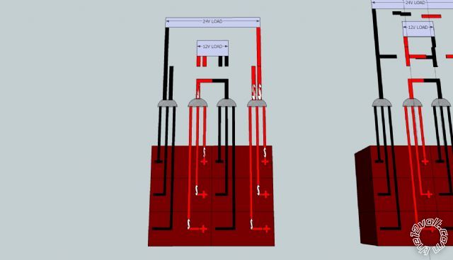 Anyway, this is how I was planning on hooking up the batteries. I need to go look up info on how the starter relay works. I'm still confused if I have to worry about damaging anything hooked up to power when I disconnect the 6 trojan batteries and then reconnect them after welding or when starting the van with all the batteries hooked up.
To be honest you lost me with a lot of what you were discussing!
I understand what you are saying about hooking all of the batteries up for cranking since the load is then split between 7-8 batteries instead of 1.
As far as the charging current being much more than it should, thats why I was trying to pick an alternator that would have a limited output between the c20 and c10 rate for the bank as a whole which is between 45-90 amps. I'm assuming that on the generator I can adjust the throttle of the motor to control the output of the the 3g/6g alternator.
I'm not sure what you are talking about with the sparks. When ever I jump start a car I put the negative on first starting with the working car then the dead car, then positive to the good car then to the dead. Removal is as you described, last on first off. Is this wrong or dangerous?
The reason for separating the battery bank in half is for better weight distribution, after all I'm adding 500lbs just from the batteries let along the mounting hardware and I want to minimize it's negative impact on the vehicles handling considering the van already handles like crap compared to a car.
Hopefully you can see in the picture what I have in mind as far as layout. By symmetric I meant that all wires from each battery will be the same length, size etc. I wanted to bring all individual battery connections from the bank to the electrical panel so that down the road if I ever build a charge controller, I can easily tie each battery into the controller as opposed to having to build one at each 1/2 of the bank because the wires are all terminated near the batteries.
I've considered relays but don't they draw electricity to activate them and hold them active? If I understand correctly, the bigger the relay, the more electricity it uses to stay activated.
At some point I would like to have a digital display that can read the batteries voltage, either one for each battery or one that is hooked to all and a switch to control which battery it will display.
I was going to run a single LED from each battery to the electrical panel, arranged to show their corresponding batteries position on the van so it is easy to visually tell if each battery is connected to the bank. This is so that I do not have to crawl under the van to check each batteries fuse if there is a problem.
The 15' is needed to get from the driver side 1/2 of the bank to the electrical panel, this also accounts for slack to do terminations and for raising and lowering the battery from under the van. I was considering putting the 1/2 bank blocks at the 1/2 bank location instead of the electrical panel, then I could run 2 1/0 cables from each 1/2 bank as opposed to 6 4ga cables from each 1/2 bank.
The plan is to always have the banks at least split in half, only the connections between the halves would be rearranged but if I understood you correctly, it is ideal to isolate batteries that are in a parallel connection.
As for the wiring, 15' of 4ga at 50 amps will drop about .18v to the 1/2 bank blocks. All connections from the 1/2 bank blocks would be in the electrical panel so their voltage drop should be much smaller than anywhere else especially since those connections will be made with 1/0. Really I was hoping to use 8 ga to the 1/2 bank blocks since their voltage drop at regular power levels won't be too much, actually 20 amps on 8 ga is about the same voltage drop as the 4ga at 50 amps. 20 amps from each battery when run at 12v is 120a/1440watts. Realistically I expect the average current draw to be about 5a per battery which equates to about 360 watts. At that power level with 8ga wire, the voltage drop is about .047v, with 4ga it's about .018v.
I'm also trying to keep the cost down where I can.
I'll look into relays but don't they drop a significant amount of voltage along with their energy usage to keep them activated? The only thing I can think of that doesn't use electricity would be switches.
Anyway, this is how I was planning on hooking up the batteries. I need to go look up info on how the starter relay works. I'm still confused if I have to worry about damaging anything hooked up to power when I disconnect the 6 trojan batteries and then reconnect them after welding or when starting the van with all the batteries hooked up.Posted: March 11, 2012 at 8:37 AM / IP Logged
PS (~8 hours after original reply) - sorting thru my bookmarks, I found one reasonable example of equal path (resistance) parallel battery connections. See Smartgauge's How to correctly interconnect multiple batteries to form one larger bank.
/end PS.
It beats me why people want deep cycle or marine batteries for cranking.
Your search for a limited alternator output is pointless - it doesn't work that way. Current limiting (if used) is required on each battery.
Yes, your jumper battery connection method is wrong - even based on conventional rules.
The simple rule for all (-ve chassis) battery connections is that WHENEVER dealing with the +ve connections, the -ve shall be disconnected - ie, -ve is off first, on last.
Relay power usage should be insignificant - usually under 250mA but more for large relays (perhaps 1A to 2A for your PAC etc).
But they are only used when the vehicle is charging or when the batteries are required, and I'd hope that their added load is negligible compared to the alternator output (and what the batteries will need to recharge). Your welder and battery capacity also make the relays insignificant when in use (though arguably your main battery should be supplying the relays). Some batteries have a self discharge current greater than what a relay uses.
But relays are essentially a convenient remote heavy-duty switch to overcome long cable lengths or negate your need to move.
But the alternative is manual connection or switches, or leaving connected and risking battery life etc.
Maybe I should have used the phrase "same path resistances" instead of symmetrical or balanced. They were not intended to mean mirror images or weight distribution.
They are not equal paths as depicted in your diagrams. You'd have to use extra fat gauge (extra cost!) to achieve that.
Did you search the web for inter-connection examples?
However, I did describe the cheaper and probably more sensible two lots of 3 in parallel arrangement.
I think you should reread my post (and my previous replies) until they gel.
I am repeating the same basic stuff, sometimes merely paraphrased or adapted as your installation detail increases.
Otherwise there are references that may express better than I.
The volmeter and LEDs should be easy (eg, 6 thin wires).
Posted: March 21, 2012 at 8:17 PM / IP Logged
I haven't had time to go back and read all of our conversations but I've gotten a few more answers.
Regarding the cabling being symmetrical, I meant resistance by using the same length of cabling and gauge regardless of physical location.
I talked to a few RV places here and one confirmed that they have used multiple relays in parallel instead of a larger one. I know that there is what is ideal but then there is reality for me in terms of what I have to spend. I have tons of the square and rectangular Ford relays, 30/40 and 20a respectively. The Highest current draw will be when welding which I don't expect more than 50 amps through each battery (3 batteries per bank, 2 banks in series, 150a welding current). The plan now is to use at least 4 of the 30/40a relays per battery so that each one is operating away from it's limit and so that multiple relay failures will not make the system fail. A single relay should be more than sufficient for normal loads considering when run as a 12v bank I will have twice the capacity which cuts the current draw in half.
I'm not sure how I want to have everything triggered to be somewhat automated but I'll figure that part out. I will either use a push button or a latching relay to control the disconnecting relays so no electricity is wasted unnecessarily.
I was thinking about the consequences of having both the vehicle alternator and the generator hooked up and powering at the same time. This seems very similar to when you jump a car, there are 2 complete electrical systems tied together. From my understanding most of the potential damage caused to equipment hooked up is from making and breaking connections while there is a load which is why for welding, I'll isolate the loads from the bank first and then rearrange the bank for 24v.
So as it stands, equal path resistance, individual disconnects for each battery, individual fuses for each battery. I'm going to work on a circuit diagram as soon as I finish figuring out what triggers etc I want to control the system.
On a side note, I'm considering replacing the stock alternator in the van with a Ford 3G just like I have for the generator and my mustang. I figure the redundancy will be good in the event that I have one die.
 Printable version
| You cannot post new topics in this forum You cannot reply to topics in this forum You cannot delete your posts in this forum You cannot edit your posts in this forum You cannot create polls in this forum You cannot vote in polls in this forum |

| Search the12volt.com |
Follow the12volt.com 
Friday, May 15, 2026 • Copyright © 1999-2026 the12volt.com, All Rights Reserved • Privacy Policy & Use of Cookies

Friday, May 15, 2026 • Copyright © 1999-2026 the12volt.com, All Rights Reserved • Privacy Policy & Use of Cookies
Disclaimer:
*All information on this site ( the12volt.com ) is provided "as is" without any warranty of any kind, either expressed or implied, including but not limited to fitness for a particular use. Any user assumes the entire risk as to the accuracy and use of this information. Please
verify all wire colors and diagrams before applying any information.
