the12volt.com spacer
icon

First Alarm, 97 Honda Civic


Post ReplyPost New Topic
< Prev Topic Next Topic >
zerovandez 
Copper - Posts: 115
Copper spacespace
Joined: March 22, 2008
Location: California, United States
Posted: June 02, 2011 at 3:08 PM / IP Logged  

So this is my understanding of what you just said...but I'm missing something...

First Alarm, 97 Honda Civic - Page 5 -- posted image.

howie ll 
Pot Metal - Posts: 16,466
Pot Metal spacespace
Joined: January 09, 2007
Location: United Kingdom
Posted: June 02, 2011 at 3:31 PM / IP Logged  
Absolutely right except I've made an error First Alarm, 97 Honda Civic - Page 5 -- posted image.
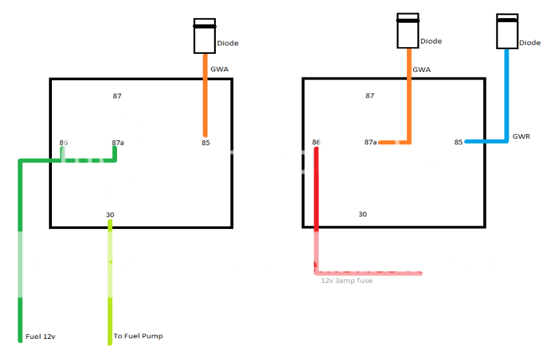
On the left relay 86 should be connected to 86 on the right relay as a constant, not from the pump feed.
on the right relay, 30 goes to 85 on the left, 87 in both relays not used.
howie ll 
Pot Metal - Posts: 16,466
Pot Metal spacespace
Joined: January 09, 2007
Location: United Kingdom
Posted: June 02, 2011 at 3:39 PM / IP Logged  
This;- relays.png
howie ll 
Pot Metal - Posts: 16,466
Pot Metal spacespace
Joined: January 09, 2007
Location: United Kingdom
Posted: June 02, 2011 at 3:44 PM / IP Logged  
Sorry, still didn't get it right, I'm lousy at graphics 277_relays.png
zerovandez 
Copper - Posts: 115
Copper spacespace
Joined: March 22, 2008
Location: California, United States
Posted: June 02, 2011 at 8:56 PM / IP Logged  
Haha! That's awesome. Thanks for taking the time to do that before I was able to revise it myself. As for the GWR output, all components using this will need to be diode isolated right? Specifically I'm referring to using for the clutch switch ground which is a direct connect without a relay right?
howie ll 
Pot Metal - Posts: 16,466
Pot Metal spacespace
Joined: January 09, 2007
Location: United Kingdom
Posted: June 03, 2011 at 12:25 AM / IP Logged  
Yes.
zerovandez 
Copper - Posts: 115
Copper spacespace
Joined: March 22, 2008
Location: California, United States
Posted: June 14, 2011 at 2:11 PM / IP Logged  
It's been a while. So I got around to more testing and probing and I found which wire needs to see ground when pressing the clutch. I played around with my DMM and set it to OHM's setting and was able to figure it out. So yay for me! Hopefully this weekend, I'll have everything mounted and mocked up to my liking. Just waiting on the DEI 530T.
howie ll 
Pot Metal - Posts: 16,466
Pot Metal spacespace
Joined: January 09, 2007
Location: United Kingdom
Posted: June 14, 2011 at 3:40 PM / IP Logged  
Some practical advice; mount the 530 in the car and run out to each door and pick up the two wires going to each motor one of which will read 12v+ on up whilst the other stays at ground and vice versa. Ignore the switches, also you have type 1 or type A windows.
I know it's a PITA to get into the doors but worth it, you will have one-touch up and down from all your switches.
zerovandez 
Copper - Posts: 115
Copper spacespace
Joined: March 22, 2008
Location: California, United States
Posted: June 14, 2011 at 5:44 PM / IP Logged  
Awesome. Thanks for the insight. The driver side door is not all that hard to get wires through. It's the passenger side that is a complete pain, litterally. The space is so tight in there as I recall running speaker wires from an amp install.
87rewire 
Member - Posts: 16
Member spacespace
Joined: November 01, 2010
Location: United States
Posted: June 14, 2011 at 6:10 PM / IP Logged  
Just reading through the thread.  What is the purpose of the diode on the gwa wire?  Is it to prevent unintentional grounding to the gwa wire?
Page of 17

  Printable version Printable version Post ReplyPost New Topic
You cannot post new topics in this forum
You cannot reply to topics in this forum
You cannot delete your posts in this forum
You cannot edit your posts in this forum
You cannot create polls in this forum
You cannot vote in polls in this forum

  •  
Search the12volt.com
Follow the12volt.com Follow the12volt.com on Facebook
Thursday, March 28, 2024 • Copyright © 1999-2024 the12volt.com, All Rights Reserved Privacy Policy & Use of Cookies
Disclaimer: *All information on this site ( the12volt.com ) is provided "as is" without any warranty of any kind, either expressed or implied, including but not limited to fitness for a particular use. Any user assumes the entire risk as to the accuracy and use of this information. Please verify all wire colors and diagrams before applying any information.

Secured by Sectigo
the12volt.com spacer
Support the12volt.com
Top
the12volt.com spacer