the12volt.com spacer
icon

corolla 2000 alarm second unlock wire


Post ReplyPost New Topic
< Prev Topic Next Topic >
mechanicalhobby 
Member - Posts: 27
Member spacespace
Joined: October 22, 2011
Location: Colorado, United States
Posted: October 22, 2011 at 6:37 PM / IP Logged  
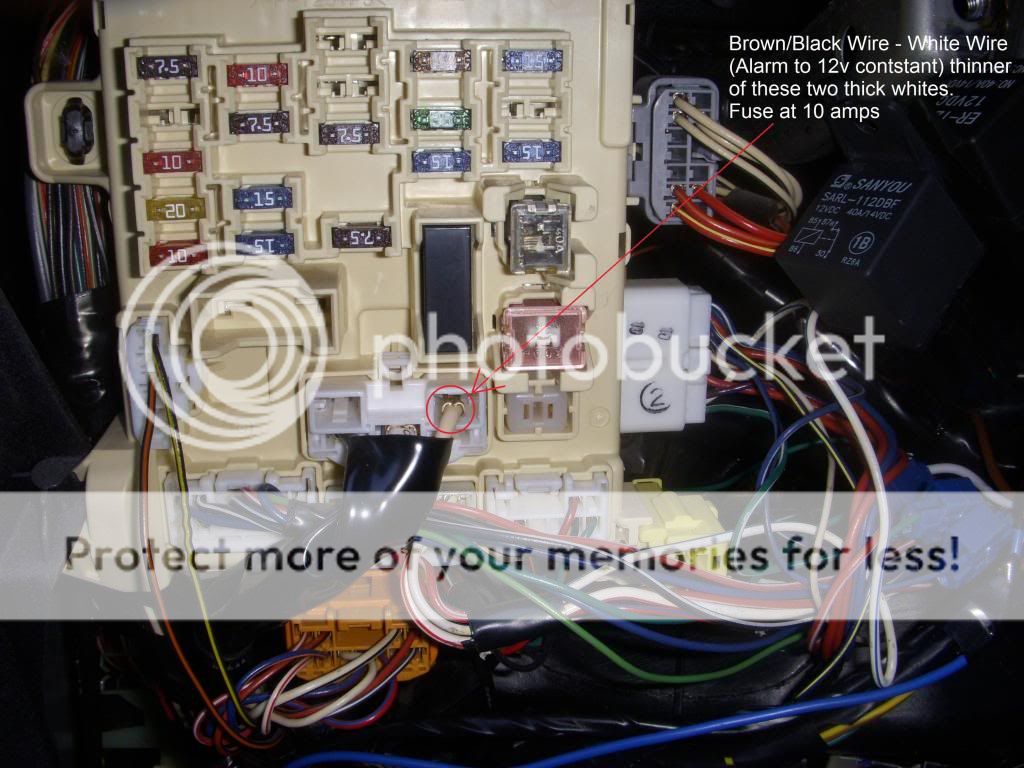
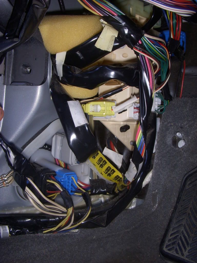
Hi,
I'm new on here, and have been installing a Remote Starter Alarm Kit (model EZ-65). I've done almost all the wiring as needed and used Google for that, which kept taking me back to this forum. I tried to follow what other people did, not necessarily the same car though, though I've managed to have get the remote start to work which originally would shut back off, so I disconnected the Tach Wire because of a weak signal on the Coils and not so good signal on the Injectors. So I connected the Oil Sensor input to the Alternator which fixed that problem. The Alarm works and the remote keyless works also, but it does not work the way I'd like it to. I've got the wiring diagrams for this Corolla on different sites that give somewhat different results, including this site which I found here:
2000 Toyota Corolla Alarm, Remote Starter, Keyless Entry Wiring Information
Basically, when I hit the unlock button on the remote, all the doors will unlock at the same time. I know how to program the kit itself, however the instructions were very vague about how to wire the Second Unlock.
The instructions state:
"Pin 2: BLUE WIRE: Second Unlock (passenger unlock)output (-) 200mA This system is equipped with a dedicated passenger unlock output allowing two stage door lock operation. When connected this wire, disarming the system will unlock only the driver s door. Pressing the disarm button again will unlock all doors..
That is exactly what it says in the instructions, spelling and all.
I need help to locate the wire and its color, where do I connect my blue wire?
During the installation, I've been taking a lot of photos to help other people once done, as there wasn't much information on the 2000 Corolla.
I've included a couple pictures of behind the driver's kick panel and the fuse box to help locating the wire.
Behind Driver's Kick Panel:
corolla 2000 alarm second unlock wire -- posted image.
Fuse Box:
(You can see two wire clamps on the right side, which connected the alarm system to both the Lock and Unlock wires as directed in the wiring diagram for this vehicle).
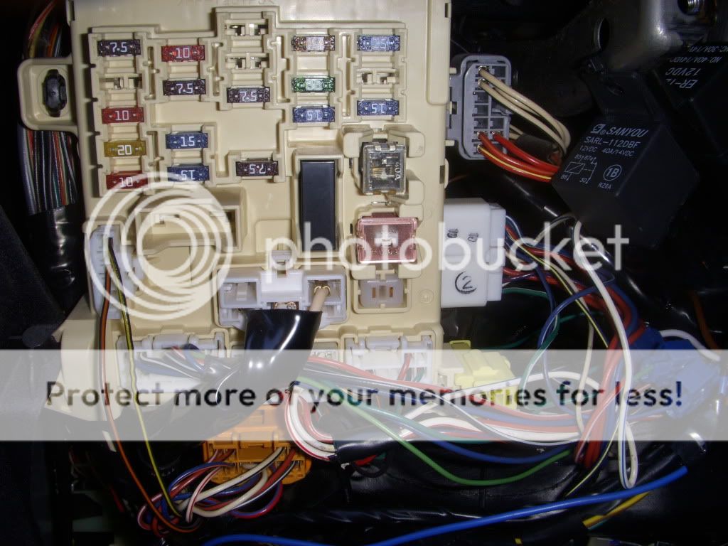
corolla 2000 alarm second unlock wire -- posted image.
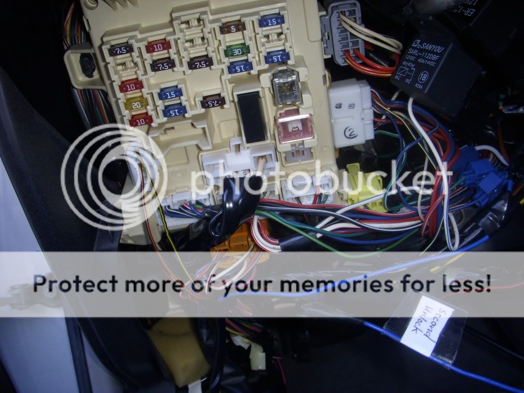
Fuse Box with Second Unlock Blue Wire (Not sure where it goes?):
corolla 2000 alarm second unlock wire -- posted image.
Any help would be very appreciated. Thanks.
PS. Not totally needed, but curious. I also have one wire for the Windows Roll Up Module. At the moment I have that wire tucked away for later. Does anyone know what I need for this? Do I need buy a special Windows Roll Up Module itself, or can I wire this PURPLE / Black Wire (-) 500mA to a wire or group of wires?
Everything else in the vehicle works perfectly, except the Second Unlock and Windows Roll Up.
howie ll 
Pot Metal - Posts: 16,466
Pot Metal spacespace
Joined: January 09, 2007
Location: United Kingdom
Posted: October 23, 2011 at 1:59 AM / IP Logged  
I'm absolutely loathe to give you advice here because any unit that doesn't pick up tach at the injectors, (odd colour wiring), the igniter, the engine management, camshaft position sensor, rear of instrument panel or pin 9 on the diagnostic socket, black with silver dots on most Toyotas is going to give you lots of problems. Picking up at the oil pressure is pretty dangerous, in fact most pros here wouldn't even touch a unit the suggests it.
Right, given my lecture, the locks. To make priority unlock work, you will need to go to the motor wires in a plug to the right in your second photo.
Let me know the number, 2 or 6, their colours and marked functions and we will take it from there.
Stop, I've just seen those scotchlocks. Totally unacceptable, there's no point in any of this, nothing will work properly.
mechanicalhobby 
Member - Posts: 27
Member spacespace
Joined: October 22, 2011
Location: Colorado, United States
Posted: October 23, 2011 at 3:18 AM / IP Logged  
howie ll wrote:
I'm absolutely loathe to give you advice here because any unit that doesn't pick up tach at the injectors, (odd colour wiring), the igniter, the engine management, camshaft position sensor, rear of instrument panel or pin 9 on the diagnostic socket, black with silver dots on most Toyotas is going to give you lots of problems. Picking up at the oil pressure is pretty dangerous, in fact most pros here wouldn't even touch a unit the suggests it.
Right, given my lecture, the locks. To make priority unlock work, you will need to go to the motor wires in a plug to the right in your second photo.
Let me know the number, 2 or 6, their colours and marked functions and we will take it from there.
Stop, I've just seen those scotchlocks. Totally unacceptable, there's no point in any of this, nothing will work properly.
Thanks for the help. In regards to the Tach Wire, my unit had two separate wires. One for the Tach and one for the Oil Sensor. The instructions said that if I used one, I have to disclude the other and vice versa. I preferred to use the Tach wire, though when I tested the odd wires on the Coils, they didn't read between 1v -6v as they are supposed to. Rather they read at 0.3v So if there revs were higher, the system would pickup the Tach Signal, but in idle, it would remote start then shut off and remote start again and do that about 3 times. So I connected the Tach Wire to the odd colored wire on the Injector and that has the same problem. So I disconnected the Tach Wire all together, and reluctantly connected the Oil Sensor Wire to the Alternator. Basically letting the unit know the car is running, and as instructed in the instructions. When I did this, the remote starter worked perfectly. Which was surprising, and still don't get it. The Instructions can be found here:
EZ-65 Alarm-RemoteStarter-KeylessEntryKit
Thanks for the heads up, those scotchlocks are temporary until I have a solid location. I had started using them at the beginning, however found the connections weren't reliable so I pulled a most of them out and soldered most of the wires. The only ones remaining now are the ones that control the doors as I want to be totally certain before soldering.
Example photo of changing to soldering for the connections below when I connected the Wire to the Alternator:
corolla 2000 alarm second unlock wire -- posted image.
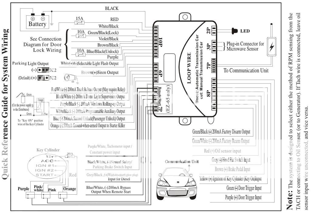
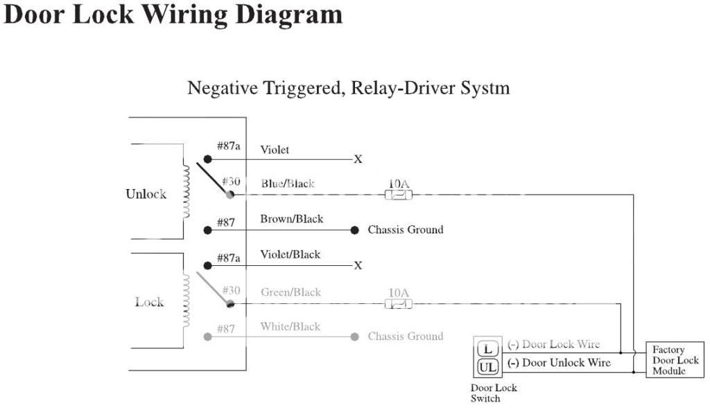
For the Door Wires, so far I've connected as follows:
The Alarm Unit's Wires used for the Doors are:
Violet - X (Closed)
Blue/Black - Chassis Ground
BROWN / Black - GREEN / WHITE (Unlock)
Violet/Black - X (Closed)
GREEN/ Black - Blue/Black (Lock)
WHITE/ Black - Chassis Ground
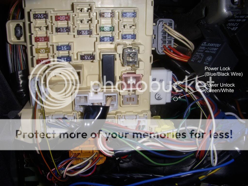
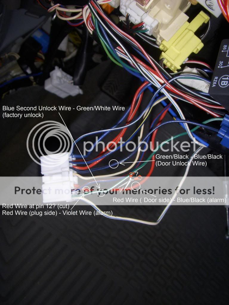
I've marked the wires used at the moment for Lock and Unlock in the following picture. Those work lock and unlock with the keyless. Though, the progressive locking is what it needed. Maybe there is a chance I need to change some wiring around.
corolla 2000 alarm second unlock wire -- posted image.
I've done a lot of wiring testing, but haven't seemed to be able to find the needed wire.
To find the correct color for the motor wires, would that be the white plug, the same plug used for the main lock and unlock wires? Would there be a good way to find these motor wires?
Just wondering, what do you mean "2 or 6"? Thanks. I really appreciate your help.
howie ll 
Pot Metal - Posts: 16,466
Pot Metal spacespace
Joined: January 09, 2007
Location: United Kingdom
Posted: October 23, 2011 at 3:42 AM / IP Logged  
OK, then you know what I as getting at, sorry for being rather harsh but...a unit that doesn't recognise tach, and I gave you some Toyota alternatives is FAULTY. Test with your DMM set to AC volts.
No matter what the alarm manual suggests, NEVER connect to the oil pressure switch, it's too unreliable.
Frankly if a customer would ask me to install this, as soon as I saw mention of the oil pressure switch I would refuse!
You are right in assuming the motor wires are in that plug, red x 2 and blue, if you bear with me I'll print a diagram but it's Sunday morning, housework and I'm going to have breakfast!
Can you copy the alarm's description of the locks?
2 wires = low current, trigger only; 6 wires, relay driven.
Ref: window close, the standard procedure would be window closers such as DEI 529t and 530t.
I have a feeling that a positive pulse applied to various wires in the DKP plugs, (the white and blue in your first picture) will raise the windows, worth testing, in the worst case you will blow a fuse.
Then all you need is a timed aux output and a relay.
What incidentally are those relays doing in the photos?
mechanicalhobby 
Member - Posts: 27
Member spacespace
Joined: October 22, 2011
Location: Colorado, United States
Posted: October 23, 2011 at 5:21 AM / IP Logged  
Thanks for your help and being strict. I'd much rather get it right then blow something that shouldn't.
I'm not a pro at the electrics, but know the basic stuff, so I may need a couple of the complicated things simplified. It was only this week that I made up my mind and sat down and learnt exactly how relays work, rather than just the concept of them. They're amazing devices!
Well, the Relays in the picture are part of the overall system. The Relay on the left is for the Remote Starter that came with the kit that cuts of the Starter once the vehicle has started. The Relay on the right I ordered online separate to a Solenoid for the Electronic Trunk Release which I also got separate since the factory standard is Cable Release near the Fuel Release Lever. After installing it all and connecting the Trunk Release Wire to the Relay, then the Relay to the Alarm, the Trunk works great!
For the Tach Wires, I tested those using DC first which read 0.1v then I did AC which read 0.3v (fluctuated a little when revs changed) which I didn't get as to why so low as it was supposed to read between 3v - 6v. I had a feeling the Oil Sensor itself was unreliable, which is why I exhausted other alternatives like the Tach, and ignored the Oil Sensor itself and opted for the 2nd choice for that wire which was the Alternator.
For the Door Locks and the Alarms Details from what I can see, there isn't a whole lot of information.
The Wiring I've done is based on a Negative Triggered, Relay-Driver System. From what I know, the 2000 Corolla uses a Negative Triggered System. The kit has 6 wires for the doors locks on the 10Pin Harness. That is the one I wired first. The Second Unlock (Blue) Wire comes from the 6Pin Harness. The Door Trigger comes from the 8Pin Harness.
Here is a couple Diagrams:
The first one is of the Kit itself, the 2nd diagram is for the doors.
corolla 2000 alarm second unlock wire -- posted image.
I can bear with you for the diagram. Thanks for your help. I'll be hitting the hay soon as it's late over here, so that's okay. Get what you need to get done, I totally understand. So far in regards to the Motor Wires, I have those labeled in this picture. Do these look correct?
corolla 2000 alarm second unlock wire -- posted image.
With the Power Windows, currently the Alarm ouputs a PURPLE / Black Wire: Auxiliary 4 Output (-) 500mA for windows rolling-up option. The instructions state: "Connect to a power window module." I wasn't sure if the 2000 Corolla has an inbuilt window module.
I did a search for the DEI 529t and 530t Window Module. If I use a timed aux output and a relay, would I then not need a DEI 529t or 530t? I bought one Relay #775 for the Trunk Release for about $15 (£9.40). Would the same type of Relay be good?
Thanks.
howie ll 
Pot Metal - Posts: 16,466
Pot Metal spacespace
Joined: January 09, 2007
Location: United Kingdom
Posted: October 23, 2011 at 7:18 AM / IP Logged  
Leave your alarm GREEN/ black connected to the car's blue/black and leave the lock side as is.
Unlock;
Red wire at pin 12 on that plug, NOT the red at pin 8.
Cut it and join the plug side to alarm's unlock violet.
Other side (door side)to alarm's unlock blue/black.
BROWN / black to 12v+ constant, fused at 10 amps. Join it to the thinner of those two thick whites going into the plug in the centre of the fuse box.
Now join the second unlock wire to the original alarm blue/black at the GREEN / WHITE factory unlock. In a previous post you said you had BROWN / black as unlock...WRONG! It should have been blue/black from the alarm, look again at the last diagram. I worry about this unit because their colours though the same as the other manufacturers, e.g. DEI aren't in the same order, they've transposed the violet and violet/black for the BROWN / black and WHITE/ black, very confusing.
White black isn't used.
Window close. Yes the wire you mentioned is the right one, but if you have a 12 volt test light with an incandescent bulb, e.g. Snap-On, Mac you can test my theory as follows. Lower the windows. Turn off the ignition and remove the key from the car. Place the clip end onto a constant 12 volts. At the driver's kick panel place the probe into every terminal on those two plugs, blue and white, yes it's fiddly. In theory if I'm right one window will close with each correct wire.
All you need then is one relay and 2 or 4 1N4004 diodes, one for each power window. Timed aux, 5 seconds, to 85, 86 and 87 to 12v+ constant at 5 amps fused, 30 via the diodes to each wire.
This will save you using one relay per window in each door, also with your method there's a chance you could burn out the window motors. 529/30 and their ilk all have limiters to prevent this.
My method if it works triggers the factory processors to prevent this.
mechanicalhobby 
Member - Posts: 27
Member spacespace
Joined: October 22, 2011
Location: Colorado, United States
Posted: October 23, 2011 at 5:26 PM / IP Logged  
I didn't remember connecting the BROWN / Black. I had a look and saw I mixed the written wires in the layout I gave earlier. Sorry. The Brown Black is not connected to the GREEN / WHITE Wire. It is connected to the
Chassis (Ground). It is Blue/Black that is connected to the GREEN / WHITE Wire as you might be able to make out in the pictures.
So the current Alarm Unit's Wires used for the doors are:
Violet - X (Closed)
Blue/Black - GREEN / WHITE (Unlock)
BROWN / Black - Chassis Ground
Violet/Black - X (Closed)
GREEN/ Black - Blue/Black (Lock)
WHITE/ Black - Chassis Ground
From the instructions you've given me which I've made out so far for the Alarm Unit's wiring will be:
Violet - Red (Plug Side at Pin 12 cut wire)
Blue/Black - Red (Alarm Side at Pin 12 cut wire)?
BROWN / Black - White (12v Constant - Thinner of two whites, Fused at 10 amps)
Violet/Black - X (Closed)
GREEN/ Black - Blue/Black (Lock)
WHITE/ Black - X (Closed)
Blue Second Unlock - GREEN / WHITE (factory unlock)
Here is a layout before I go cutting to confirm these wires:
For the Red Wire, is it the bottom wire or the top wire. I tried doing a count, but counting in different ways gave different results. Just was to be sure.
corolla 2000 alarm second unlock wire -- posted image.
For the Power Windows, I could drop into an Electronic Store and pick some of those parts up. I'm getting what you are saying about the Diodes. I have 4 Power Windows, so would that require 4 1N4004 Diodes?
You mentioned Timed Aux, would I have to wire these to time it, or get a relay that is timed? It would be good have the Windows roll up and cut off power to them automatically when they fully close. Is this possible?
So the wiring for the Relay on this would be:
85, 86 and 87 connect to a 12v+ Constant (5 amps fused)
30 connect with 4 1N4004 Diodes to each Window roll up Wire
Doing this will no longer require a 529/30 Window Module?
I'm starting to get a grasp on all this. Just need to be certain before I go cutting and splicing anymore wires. Thanks for your help.
howie ll 
Pot Metal - Posts: 16,466
Pot Metal spacespace
Joined: January 09, 2007
Location: United Kingdom
Posted: October 23, 2011 at 6:04 PM / IP Logged  
Ref your last list
Blue/black from the alarm is joined to the door side of the cut driver's door red wire.
WHITE/ black to chassis ground. Violet/black isn't used.
The other WHITE/ black is your programmable output, I'm assuming this can be set to timed.
But first if I'm wrong about checking those wires in the DKP plugs, you will have to use the PURPLE / black with a 529t or the PURPLE / black and WHITE/ black (to allow venting) with the 530t.
mechanicalhobby 
Member - Posts: 27
Member spacespace
Joined: October 22, 2011
Location: Colorado, United States
Posted: October 23, 2011 at 7:14 PM / IP Logged  
For the wiring, this is what I've got now.
Violet - Red (Plug Side at Pin 12 cut wire)
Blue/Black - Red (Door Side at Pin 12 cut wire)?
BROWN / Black - White (12v Constant - Thinner of two whites, Fused at 10 amps)
Violet/Black - X (Closed)
GREEN/ Black - Blue/Black (Lock)
WHITE/ Black - Chassis Ground
Blue Second Unlock - GREEN / WHITE (factory unlock)
Does this all look right for the door locks? Am I cutting into the correct red wire?
corolla 2000 alarm second unlock wire -- posted image.
If I've got these down right, I'll be rewiring them today.
For the Windows:
The other WHITE/ Black Wire, is that the one on the 6Pin Harness for Aux Output?
If so, the Auxiliary Channel 5 Output can be programmed with 3 options as follows:
Option 1: 0.8 second pulse
Option 2: 15 seconds pules
Option 3: Latched Output
There is no programming option for the Auxiliary 4 Output for Windows Rolling-up option
The actual Window roll up wire is also (-) 500mA.
The color of the Window roll up wire is a PURPLE / Black Wire.
Would it be better to use this wire? (since it sends a signal to roll up all the windows at the arming command automatically, whereas the Aux 5 is manual and could be used for another feature.)
I'll check the DKP plugs today and let you know what I find.
howie ll 
Pot Metal - Posts: 16,466
Pot Metal spacespace
Joined: January 09, 2007
Location: United Kingdom
Posted: October 24, 2011 at 1:31 AM / IP Logged  
Yes to your questions, test the purple black, see if it shuts off after a few seconds.
Ref: the the red wires, the one you want is 12, the one you don't want is 8 and the blue is 7, thus don't use the red adjacent to the blue, if you get it wrong, no harm, you will simply unlock the passenger door first instead of the driver's door.
Page of 3

  Printable version Printable version Post ReplyPost New Topic
You cannot post new topics in this forum
You cannot reply to topics in this forum
You cannot delete your posts in this forum
You cannot edit your posts in this forum
You cannot create polls in this forum
You cannot vote in polls in this forum

  •  
Search the12volt.com
Follow the12volt.com Follow the12volt.com on Facebook
Thursday, April 25, 2024 • Copyright © 1999-2024 the12volt.com, All Rights Reserved Privacy Policy & Use of Cookies
Disclaimer: *All information on this site ( the12volt.com ) is provided "as is" without any warranty of any kind, either expressed or implied, including but not limited to fitness for a particular use. Any user assumes the entire risk as to the accuracy and use of this information. Please verify all wire colors and diagrams before applying any information.

Secured by Sectigo
the12volt.com spacer
Support the12volt.com
Top
the12volt.com spacer