the12volt.com spacer
icon

door lock wire color on 2009 mazda5


Post ReplyPost New Topic
< Prev Topic Next Topic >
twintrbo 
Member - Posts: 20
Member spacespace
Joined: December 20, 2011
Location: New York, United States
Posted: December 20, 2011 at 9:57 PM / IP Logged  
Im doing a remote start and keyless entry on a 2009 Mazda5. I think the wiring is different from year to year and I'm finding info that tells me to tap the Blue wire in the driver kick panel. I want to be sure this is the right info since the factory service manual I have does not even show a blue wire in the system. I also bought a DEI 451m module to interface with the factory setup, so if anyone could verify that connection I would really appreciate it. Oh and yes I do have a transponder bypass as well. Thanks in advance.
birdman41 
Member - Posts: 16
Member spacespace
Joined: December 07, 2011
Location: Arizona, United States
Posted: December 21, 2011 at 3:57 AM / IP Logged  
From what I found..the blue wire is the lock/unlock wire in the driver kick panel or behind glovebox at BCM.
http://www.bulldogsecurity.com/bdnew/vehiclewiringdiagrams.asp
twintrbo 
Member - Posts: 20
Member spacespace
Joined: December 20, 2011
Location: New York, United States
Posted: December 21, 2011 at 7:42 AM / IP Logged  
Yes, that's where I got my info from. I just wanted someone who knows for sure to confirm it. I found conflicting information out there and want to be sure. Also do I hook up my relays to go to ground once activated from the alarm brain? I know I need a 1000k resistor on the unlock wire.
howie ll 
Pot Metal - Posts: 16,466
Pot Metal spacespace
Joined: January 09, 2007
Location: United Kingdom
Posted: December 21, 2011 at 11:36 AM / IP Logged  
Yes you will need relays if the R/S only has a 2 wire lock output, WHITE/ black and BROWN / black, don't use and tape up.
Violet and violet/black to a good ground.
Blue/black, wire your resistor in line then join to GREEN/ black and then to the blue wire.
twintrbo 
Member - Posts: 20
Member spacespace
Joined: December 20, 2011
Location: New York, United States
Posted: December 21, 2011 at 3:41 PM / IP Logged  
Looks like I was on the right path then. Howie, you have earned your gold status in my book! I have 2 other questions, if you dont mind.
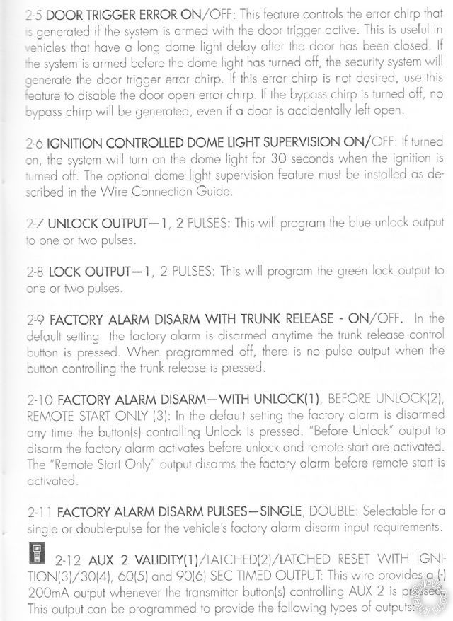
My Python 533 has a wire for a -200mA 2nd unlock output. Do I need this to unlock all the doors at once or can this be accomplished with programming the module for 2, instead of 1, unlocking pulses on the relays? Its confusing to me because, if so, I dont see a point for the second wire in the first place.
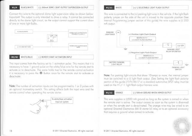
Question 2 is they show a button attached to a (-) remote start activation input wire. It says I need 1 ground pulse on this wire for the remote start to activate or deactivate. Should I hook this up to the -200mA status output wire that supplies the pulse when the remote start process begins? I am confused because this would be hooking up wires from the same unit that I would think should be wired internally.
Thanks again, I'm going to get started on this perhaps tomorrow and I cant wait!
howie ll 
Pot Metal - Posts: 16,466
Pot Metal spacespace
Joined: January 09, 2007
Location: United Kingdom
Posted: December 21, 2011 at 6:42 PM / IP Logged  
Thanks but I've been a Platinum member twice before but they keep demoting me because I've no patience with morons who won't listen/think they know it all without testing.
1) The second wire is for priority unlock. i.e. driver's door initially, then the others only if you activate 2nd unlock.
You will have to slightly mod your 451 but here's how:- 9A9_multiplex_priority_unlock.bmp
Note you are going to have to mod the 451. One, either the violet or violet/black (the lock side ) goes to ground, the other side goes to 12v+ constant.
2) If the wire you are referring to is BLACK/ white, ground it through the switch with an auto, or straight to your reverse light feed.
If manual to the parking brake switch.
twintrbo 
Member - Posts: 20
Member spacespace
Joined: December 20, 2011
Location: New York, United States
Posted: December 22, 2011 at 8:02 AM / IP Logged  
Well thats not fair to you at all. My 5 year old learned from other kids that crying will you get you what you want, and get other people in trouble, so I guess that how some people still try to get through life. Thanks for your help on this, the manual for this thing really stinks, very vague and there isn't any tech support from DEI on it either. Im an electrician by trade, and this is my 3rd alarm install so its pretty humbling to not know exactly what I'm doing this time around.
As for the priority unlocking, I dont want it that way if possible. I want them all to unlock since its a family car. Frankly, I think its a stupid option in the first place. All the doors should open, if you want only the one door, and the remote and key are in your hand, use the key.... I thought thats what was the 2 pulses on the unlock wire was for. Is that an option for another type of system? Im attaching a scan of the manual, its file Python533.2 Item 2-7
The other wire I was asking about is WHITE/ Blue. Its not the neutral safety switch. I scanned this as well, file Python533.1 wire H1/10
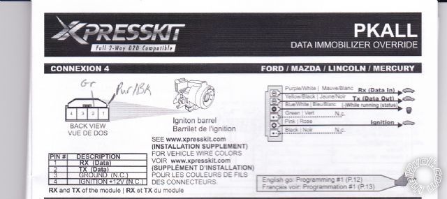
Lastly, the PKALL transponder unit needs a Pink wire to +12v Ignition, is there a reason I cant take it from the 4 pin bus connector at the Ignition switch where I'm tapping the TX and RX wires? It says N.C. in the PKALL manual for that pin, which I take to mean no connection, but it seems a logical place to feed it from. I scanned that one as PKALL.
Thanks again for all your help in this install. Is there a standard wiring code for alarms BTW? That might help me figure some of this out on my own.
door lock wire color on 2009 mazda5 -- posted image.
twintrbo 
Member - Posts: 20
Member spacespace
Joined: December 20, 2011
Location: New York, United States
Posted: December 22, 2011 at 9:06 AM / IP Logged  
Thinking about it, I believe that WHITE/ blue is just a way to start the sequence without the remote. Consider that one solved :)
howie ll 
Pot Metal - Posts: 16,466
Pot Metal spacespace
Joined: January 09, 2007
Location: United Kingdom
Posted: December 22, 2011 at 9:31 AM / IP Logged  
Then ignore the second unlock wire, just leave it as was before.
Blame the US for priority unlocking, the Scandinavians for daytime running lights and the Germans for immobilisers!
Don't use the WHITE/ blue as you thought.
Better to take from the main ignition 1 wire, otherwise you might get
data related problems.
By the way, with regards to switches and relays, NC usually means normally closed such as 30 and 87a so be very careful there.
twintrbo 
Member - Posts: 20
Member spacespace
Joined: December 20, 2011
Location: New York, United States
Posted: December 22, 2011 at 10:51 AM / IP Logged  
Ok then I will just hook up the door locks as normal and change the programming for 2 pulses. I will also take the pink from the PKALL and take it to the regular ignition wire. I figured it might cause some issues, glad I asked! As for the WHITE/ blue, I guess I will get a momentary switch eventually so I can hook it up. I dont think I will use it ever, it may be useful for testing the system if I ever need to.
I know about the NC for relays and switches. In that diagram though, I'm pretty sure its referring to wire connections only. Thats why I assume its No Connection in that instance and why they seem to be steering you from taking power from that source. Thanks again, you have been incredibly helpful and I'll let you know the results. FWIW I will be posting this as a DIY over at the Mazda5 Forum once its done.
Page of 5

  Printable version Printable version Post ReplyPost New Topic
You cannot post new topics in this forum
You cannot reply to topics in this forum
You cannot delete your posts in this forum
You cannot edit your posts in this forum
You cannot create polls in this forum
You cannot vote in polls in this forum

  •  
Search the12volt.com
Follow the12volt.com Follow the12volt.com on Facebook
Monday, May 6, 2024 • Copyright © 1999-2024 the12volt.com, All Rights Reserved Privacy Policy & Use of Cookies
Disclaimer: *All information on this site ( the12volt.com ) is provided "as is" without any warranty of any kind, either expressed or implied, including but not limited to fitness for a particular use. Any user assumes the entire risk as to the accuracy and use of this information. Please verify all wire colors and diagrams before applying any information.

Secured by Sectigo
the12volt.com spacer
Support the12volt.com
Top
the12volt.com spacer