the12volt.com spacer
icon

2009-2011 Toyota Yaris Remote Starter Pictorial


Post ReplyPost New Topic
< Prev Topic Next Topic >
windog 
Member - Posts: 4
Member spacespace
Joined: September 30, 2009
Location: Manitoba, Canada
Posted: April 03, 2017 at 1:20 AM / IP Logged  
The door trigger polarity has to be determined before connections are made. If the door trigger wire reads negative when the door is open then you have to connect the trigger wire on the vehicle to the negative trigger wire on your remote starter or alarm device. Do the reverse process if the door trigger tests positive polarity when the door is open. You should not connect the wires without diode connection, The diodes are for protection of your remote starter or alarm device and for your safety too. You could start a fire in the car if there is feedback from your door pin to the vehicle's circuitry.
hoanayang 
Member - Posts: 7
Member spacespace
Joined: January 30, 2017
Location: California, United States
Posted: April 03, 2017 at 1:39 AM / IP Logged  
Thank you for the quick reply!
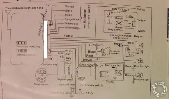
May I know more detail about how to determine negative or positive reading? The reason I am asking because door wire is only one wire (pin 22 for the driver side, and pin 5 for the passenger side)
when I use the multireader, I connect red terminal to pin 22, and the black terminal to the car body. I got the value of 4.97V when the door is close. when the door is open I got 0V. (the weird thing is that about 30 seconds after the door closing, the reading from 4.97V becomes to 1.98V, but this doesn't effect the result with a diode)
I also did the test for the alarm door trigger wire to the car body, it is constaint of 4.76V
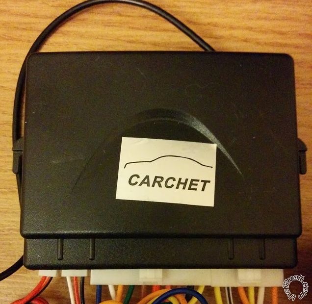
When I connect the alarm door trigger wire to pin22, when the door open, it become 0V too and the door trigger is triggered correctly. However, if I have a diode in between, the reading is 0.7V, and the door trigger is not triggered.
Thank You!
kreg357 
Platinum - Posts: 7,780
Platinum spaceThis member has made a donation to the12volt.com. Click here for more info.spaceThis member has been recognized as an authority in Electrical Theory. Click here for more info.spaceThis member has been recognized as an authority in Mobile Security and Convenience. Click here for more info.spacespace
Joined: January 30, 2009
Location: Pennsylvania, United States
Posted: April 03, 2017 at 6:05 PM / IP Logged  
With a Digital Multi Meter you must use a kind of reverse logic. You are looking for a ground potential when the door is opened. It takes a bit of thought to figure how to read this ground. Basically you must look for a ground path that will complete a simple circuit. If you place the DMM Red lead on the batterys' positive terminal and have the Black lead touching nothing, the meter will read 0V. When you touch the Black lead to the negative battery terminal ( or any solid chassis point ), the DMM will read +12V. That is the way to test. Connect the Red lead to +12V constant and the Black lead to the suspect Door Trigger wire. With the door closed you should get 0V. When the door is opened, the Black lead now has path back to the battery and the DMM will read +12V.
Kind of like that old brain teaser, where you are walking down a road and come to a fork. One way leads to your destination, the other way goes in the wrong direction. At the fork are two brothers. One always tells the truth and the other always lies. You get to ask one and only one question of one brother but you don't know which one is which. What is your question that will get you heading down the correct path?
Soldering is fun!
hoanayang 
Member - Posts: 7
Member spacespace
Joined: January 30, 2017
Location: California, United States
Posted: April 03, 2017 at 6:33 PM / IP Logged  
thank you. I will test it tonight when I get home.
By the way, I read all document, and they all mention negative door trigger. does that mean I have to use negative trigger wire in the alarm?
Door Trigger Negative Wire (-): Pink
Door Trigger Negative Wire Location: At Fuse Panel Behind the Driver Side of the Dash
modified life web /2009-toyota-yaris-auto-alarm-wiring-instructions/
I tried the horn, the document said it is negative, but my alarm produce positive so I need to use a relay to convert it back to negative. then it works without any issue. I wonder is the same way alarm trigger?
thanks
hoanayang 
Member - Posts: 7
Member spacespace
Joined: January 30, 2017
Location: California, United States
Posted: April 03, 2017 at 10:36 PM / IP Logged  
very interesting. I follow your step.
When the door is open:
  • DMM red to battery positive, DMM black to the door trigger wire = 12.65V
  • DMM black to battery negative, DDM red to the door trigger wire = 0V
When the door is close:
  • DMM red to battery positive, DMM black to the door trigger wire = 0V
  • DMM black to battery negative, DDM red to the door trigger wire = 5.21V
Questions:
Thanks a lot!
2009-2011 Toyota Yaris Remote Starter Pictorial - Page 4 - Last Post -- posted image.
Page of 4

Sorry, you can NOT post a reply.
This topic is closed.

  Printable version Printable version Post ReplyPost New Topic
You cannot post new topics in this forum
You cannot reply to topics in this forum
You cannot delete your posts in this forum
You cannot edit your posts in this forum
You cannot create polls in this forum
You cannot vote in polls in this forum

  •  
Search the12volt.com
Follow the12volt.com Follow the12volt.com on Facebook
Tuesday, March 19, 2024 • Copyright © 1999-2024 the12volt.com, All Rights Reserved Privacy Policy & Use of Cookies
Disclaimer: *All information on this site ( the12volt.com ) is provided "as is" without any warranty of any kind, either expressed or implied, including but not limited to fitness for a particular use. Any user assumes the entire risk as to the accuracy and use of this information. Please verify all wire colors and diagrams before applying any information.

Secured by Sectigo
the12volt.com spacer
Support the12volt.com
Top
the12volt.com spacer