the12volt.com spacer
icon

viper 5901 wiring into 94 celica


Post ReplyPost New Topic
< Prev Topic Next Topic >
dasbogie 
Silver - Posts: 514
Silver spacespace
Joined: September 30, 2006
Location: Pennsylvania, United States
Posted: May 23, 2012 at 5:29 PM / IP Logged  
Is this celica a manual transmission?  I believe the manual for the 5901 is posted on this site in the downloads section
Advanced
ask92 
Member - Posts: 34
Member spacespace
Joined: August 08, 2011
Posted: May 23, 2012 at 7:37 PM / IP Logged  
Yes its a manual. I have all the documentation for the 5901 and have searched every one for "reservation mode" with no avail.
tony_g 
Copper - Posts: 86
Copper spacespace
Joined: November 26, 2010
Location: Alberta, Canada
Posted: May 24, 2012 at 1:47 AM / IP Logged  

7 light flashes means its in manual transmission mode but reservation mode has not been initialised.

If the vehicle has a manual transmission the proper steps must be followed

before leaving the parked vehicle or the remote start feature is disabled.

1. Make sure the engine is running and the doors on the vehicle are closed.

2. Put the transmission in neutral.

3. Press on the foot brake in the vehicle.

4. Apply the emergency brake.

5. Release the foot brake.

Note: Pressing the brake pedal again after this step will disable the remote start feature.

6. Within 15 seconds activate the remote start from the remote.

7. The parking lights flash 5-times confirming that the remote start is active.

If the parking lights do not flash 5-times, then repeat steps 1 - 6.

8. Turn off the ignition (the car stays running when key is turned off).

9. exit vehicle

10. Arm the alarm (the vehicle should shut off when arming the system).

if the alarm is triggered whilst armed then the now set reservation mode will be cancelled as the alarm assumes someone may have gained access into the vehicle and potentially could have knocked the transmission into gear which would be a potential risk if remote started so you would have to disarm and go through the steps from 1 to 10 again after an alarm trigger

tony_g 
Copper - Posts: 86
Copper spacespace
Joined: November 26, 2010
Location: Alberta, Canada
Posted: May 24, 2012 at 1:58 AM / IP Logged  
page 28 of the user/owners guide in case its needed for future reference
kreg357 
Platinum - Posts: 7,783
Platinum spaceThis member has made a donation to the12volt.com. Click here for more info.spaceThis member has been recognized as an authority in Electrical Theory. Click here for more info.spaceThis member has been recognized as an authority in Mobile Security and Convenience. Click here for more info.spacespace
Joined: January 30, 2009
Location: Pennsylvania, United States
Posted: May 24, 2012 at 6:22 AM / IP Logged  

Additional info :   ( From 5901 Install Guide )

Remote start MTS mode failure

The remote emits a failure notification when trying to enable the manual transmission
mode or the vehicle fails to stay remote started when the key is turned off.
Possible causes are:
• Hood Open (gray wire).
• Foot Brake active (brown wire).
• No Parking Brake input, BLACK/ white neutral safety wire not showing ground with parking brake set.
• Tachometer is not hooked up or programmed.    ****
• The unit has not been programmed for tachometer mode   ****
• Toggle switch not installed or not in the ON position.

As you can see, the Viper monitors and uses the following signals to enable Manual Transmission Mode : 

Neutral Safety Switch input, Brake Pedal and Door Trigger ( either + or - )    All of these inputs must be connected.

****  As noted, for Manual Tranmission Mode,  the Vipers Engine Checking Mode must be set to Tach  ( Menu 3, Item 2,

Option 4 ) and the Tach Learn  process successfully completed. 

Soldering is fun!
ask92 
Member - Posts: 34
Member spacespace
Joined: August 08, 2011
Posted: May 24, 2012 at 10:34 AM / IP Logged  
Ok I am almost positive I have done those steps before and nothing happened, so ill check all my wiring today. My other issue is the parking lights are not hooked up, so I dont know when they flash. The person that helped me install the alarm(from here) seemed to imply they are not required. If someone could look the wiring over and tell me which wires need to be connected for the parking lights to work I would greatly appreciate it. Thank you the12volt.com!!!!
Link to the wiring
kreg357 
Platinum - Posts: 7,783
Platinum spaceThis member has made a donation to the12volt.com. Click here for more info.spaceThis member has been recognized as an authority in Electrical Theory. Click here for more info.spaceThis member has been recognized as an authority in Mobile Security and Convenience. Click here for more info.spacespace
Joined: January 30, 2009
Location: Pennsylvania, United States
Posted: May 24, 2012 at 11:02 AM / IP Logged  

Parking Lights :  Set the Vipers internal Parking Light fuse/jumper to (-)

Locate and verify this wire :  Parking Lights (-)        Light Green          @ steering column

Connect the Vipers H1/11 White wire to the above wire. ( H1/4 is not used.)

Soldering is fun!
ask92 
Member - Posts: 34
Member spacespace
Joined: August 08, 2011
Posted: May 24, 2012 at 2:17 PM / IP Logged  
Ok so I got the parking wires all working now. However now when I have everything fully hooked up and the clutch switch just simply shorted when I turn the key to start the car normally the starter just continues to spin and I have to unhook the battery. I am thinking I have something setup wrong with h3.
Here is the diagram:
viper 5901 wiring into 94 celica - Page 4 -- posted image.
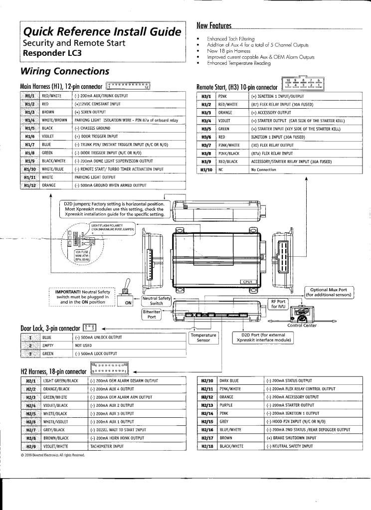
The questionable wires are H3/4 which I have connected directly to the start signal wire in the engine bay. Correct or not?
h3/5 is hooked up to to the wire that is said to be starter near the ignition itself.
H3/2,h3/6 and h3/9 are all connected directly to 12 volts. Correct or not?
kreg357 
Platinum - Posts: 7,783
Platinum spaceThis member has made a donation to the12volt.com. Click here for more info.spaceThis member has been recognized as an authority in Electrical Theory. Click here for more info.spaceThis member has been recognized as an authority in Mobile Security and Convenience. Click here for more info.spacespace
Joined: January 30, 2009
Location: Pennsylvania, United States
Posted: May 24, 2012 at 2:35 PM / IP Logged  

All connections should be made at the steering column / ignition switch harness.

All wires should be verified before making any connections.   ( Info from Bulldog Security.)

Viper H3 harness     '94 Celica

H3/1 PINK (+) IGNITION 1 INPUT/OUTPUT    BLACK/ Orange @ Ignition Switch
H3/2 RED / WHITE (+) FUSED (30A)       White @ Ignition Switch
H3/3 ORANGE (+) ACCESSORY OUTPUT       Gray @ Ignition Switch
H3/4 VIOLET (+) STARTER OUTPUT (CAR SIDE)     BLACK/ White @ Ignition Switch - cut  **
H3/5 GREEN (+) STARTER INPUT (KEY SIDE)         BLACK/ White @ Ignition Switch - cut  **
H3/6 RED (+) FUSED (30A) IGNITION 1 INPUT         BLACK/ Red @ Ignition Switch
H3/7 PINK/WHITE (+) IGNITION 2        Blue/Red @ Ignition Switch  ***
H3/8 PINK/BLACK (+) FLEX RELAY 87A         Not Used
H3/9 RED / BLACK (+) FUSED (30A)    White @ Ignition Switch
H3/10 NC (no connection)

** Note that Starter Kill / Anti-Grind is optional.  If you don't want / need this

feature, do not cut the Celica's BLACK/ White Starter wire and only connect / use
the Vipers H3/4 Violet wire ( H3/5 would not be connected / used ).

*** Viper default is H3/7 = Ignition2   Verify this programming option.

Soldering is fun!
kreg357 
Platinum - Posts: 7,783
Platinum spaceThis member has made a donation to the12volt.com. Click here for more info.spaceThis member has been recognized as an authority in Electrical Theory. Click here for more info.spaceThis member has been recognized as an authority in Mobile Security and Convenience. Click here for more info.spacespace
Joined: January 30, 2009
Location: Pennsylvania, United States
Posted: May 24, 2012 at 2:51 PM / IP Logged  

Very IMPORTANT warning :  

"Just shorting" the clutch pedal interlock switch is very bad.  Your car

will now start with the key, without the clutch pedal depressed.  This is
very dangerous if the transmission is not in neutral.  Please reference
Note 3 from the original instructions that were given in the link you posted
and implement that relay for safeties sake.

Soldering is fun!
Page of 6

  Printable version Printable version Post ReplyPost New Topic
You cannot post new topics in this forum
You cannot reply to topics in this forum
You cannot delete your posts in this forum
You cannot edit your posts in this forum
You cannot create polls in this forum
You cannot vote in polls in this forum

  •  
Search the12volt.com
Follow the12volt.com Follow the12volt.com on Facebook
Thursday, May 2, 2024 • Copyright © 1999-2024 the12volt.com, All Rights Reserved Privacy Policy & Use of Cookies
Disclaimer: *All information on this site ( the12volt.com ) is provided "as is" without any warranty of any kind, either expressed or implied, including but not limited to fitness for a particular use. Any user assumes the entire risk as to the accuracy and use of this information. Please verify all wire colors and diagrams before applying any information.

Secured by Sectigo
the12volt.com spacer
Support the12volt.com
Top
the12volt.com spacer