the12volt.com spacer
icon

heated mirrors, 2010 fj cruiser


Post ReplyPost New Topic
< Prev Topic Next Topic >
gromov 
Member - Posts: 13
Member spacespace
Joined: February 14, 2012
Location: Azerbaijan
Posted: February 14, 2012 at 1:21 PM / IP Logged  
Hi Everibody,
i'm a bit of a retard when it comes to electrical stuff.
I will be installing heated mirrors on my 2010 FJ cruiser. The plan is to hook them up to the rear defog button for simplicity. Assuming that i will find the right wire that goes to rear window defogger and tap into it
1.) will i need to add an inline fuse between the point of tap and the heating pad?
2.) Where do i ground the heat pads?
Thanks!
pts760 
Copper - Posts: 403
Copper spacespace
Joined: December 11, 2009
Location: United States
Posted: February 14, 2012 at 4:13 PM / IP Logged  
Use a SPDT 30/40A relay to isolate the circuit at the defrost switch from the heated pads. Use a inline fuse from the power source at the relay to the heated pads (fuse according to the heated pads current consumption).
Trigger must be a timed output otherwise the pads will only engage when the button is depressed.
If negative trigger at switch:
86: 12v (fused)
85: (-) trigger from defrost switch
87: 12v (fused- you can tie 86 & 87 together)
87a: Not Used
30: positive lead at headed pad
If positive trigger at switch:
86: (+) at switch
85: Ground
87: 12v
87a: Not Used
30: positive lead at headed pad
Make sure you ground the pads to bare metal/chassis.
I drink current, eat ohms, and bleed voltage
flobee4 
Silver - Posts: 585
Silver spacespace
Joined: January 02, 2004
Location: United States
Posted: February 14, 2012 at 10:11 PM / IP Logged  
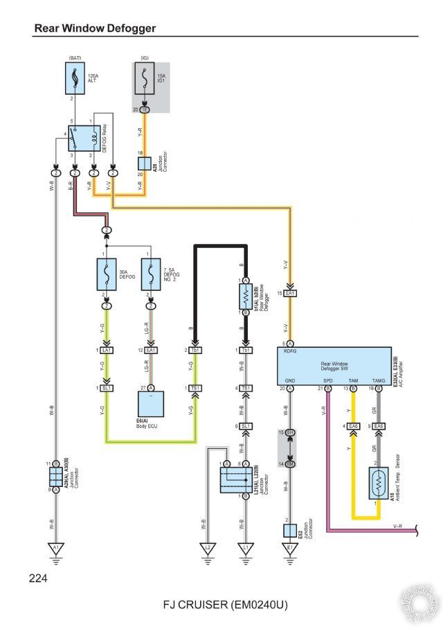
Here is the factory wiring diagram, The yellow/purple wire leaving the defogger switch and going to the defogger relay is your low power negative wire. It is located in a blue connector in the drivers kick panel. The output of the relay is YELLOW /GREEN and Positive. It is located running down the drivers side floor harness(under the drivers door sill plate)
heated mirrors, 2010 fj cruiser -- posted image.
gromov 
Member - Posts: 13
Member spacespace
Joined: February 14, 2012
Location: Azerbaijan
Posted: February 14, 2012 at 11:55 PM / IP Logged  
wow thanks guys.
pts760 before last night relays looked like nuclear physics to me, but a simple google search proved it otherwise, now its all good and clear and I am of a strong opinion that the relays are the way to go.
However some folks on fjcruiserforums.com wired them directly to the positive trigger without any relays claiming that heat pads do not draw too much current.
flobee4 thanks. Yes I've done some research and found out that YELLOW /GREEN wire needs to be tapped in. Should i try to solder or Posi Tap will do the job?
tedmond 
Gold - Posts: 4,610
Gold spaceThis member has been recognized as an authority in Mobile Security and Convenience. Click here for more info.spacespace
Joined: January 06, 2007
Location: Ontario, Canada
Posted: February 15, 2012 at 12:16 AM / IP Logged  
solder only
its actually yellow/purple in the driver kick panel (-) 8min latched
blue 18pin plug
Ted
2nd Year Tier 1 Medical School
Still installing as a hobby...pays for groceries
Compustar Expert
gromov 
Member - Posts: 13
Member spacespace
Joined: February 14, 2012
Location: Azerbaijan
Posted: February 15, 2012 at 3:39 AM / IP Logged  
Since i've opened this topic, i found another write up on heated mirrors on Tacoma and the guy used the OEM Mirror heater button, so i guess I will try to go that way instead of tying mirrors to rear defog.
Here's the link for the writeup. it does seems more complex, but the end result is just so much better. Tacoma Heated Mirrors
awdeclipse 
Copper - Posts: 285
Copper spacespace
Joined: August 05, 2007
Location: Michigan, United States
Posted: February 15, 2012 at 8:41 AM / IP Logged  
Nice write up. I would skip all those "quick splice" connectors though. Just solder and heat shrink those connections instead. Especially because all those wires shown that used a "quick splice" were wires added for the project. And while you are soldering those connections, might as well skip the butt-connectors too.
gromov 
Member - Posts: 13
Member spacespace
Joined: February 14, 2012
Location: Azerbaijan
Posted: February 15, 2012 at 11:00 AM / IP Logged  
yeah, planning on soldering connections instead of t-taps and quick splices.
this brings me to my next dilemma, obviously since the car is outside and i dont have a garage i will need a cordless soldering iron.
should i get Weller butane one or battery powered ones? It seems to me batteries will be dying very soon and with butane one i could also shrink the heatshrinks.
tedmond 
Gold - Posts: 4,610
Gold spaceThis member has been recognized as an authority in Mobile Security and Convenience. Click here for more info.spacespace
Joined: January 06, 2007
Location: Ontario, Canada
Posted: February 15, 2012 at 11:17 AM / IP Logged  
battery irons are not that great. The butane one works very well, as long as you don't place it on the carpet by accident.
I used to use the weller pyropen/pyropen JR, but changed to a MAC tools one since it was much cheaper to buy. if you don't solder often, get a 20 dollar wired one, and use an extension cord
Ted
2nd Year Tier 1 Medical School
Still installing as a hobby...pays for groceries
Compustar Expert
gromov 
Member - Posts: 13
Member spacespace
Joined: February 14, 2012
Location: Azerbaijan
Posted: February 15, 2012 at 1:05 PM / IP Logged  
I have this fetish for tools to be honest and try to buy tools whenever I can justify their purchase to wife :D So i'm just putting an order thru for Weller PSI100k and other bits I will need for the install.
Page of 2

  Printable version Printable version Post ReplyPost New Topic
You cannot post new topics in this forum
You cannot reply to topics in this forum
You cannot delete your posts in this forum
You cannot edit your posts in this forum
You cannot create polls in this forum
You cannot vote in polls in this forum

  •  
Search the12volt.com
Follow the12volt.com Follow the12volt.com on Facebook
Thursday, April 25, 2024 • Copyright © 1999-2024 the12volt.com, All Rights Reserved Privacy Policy & Use of Cookies
Disclaimer: *All information on this site ( the12volt.com ) is provided "as is" without any warranty of any kind, either expressed or implied, including but not limited to fitness for a particular use. Any user assumes the entire risk as to the accuracy and use of this information. Please verify all wire colors and diagrams before applying any information.

Secured by Sectigo
the12volt.com spacer
Support the12volt.com
Top
the12volt.com spacer