the12volt.com spacer
icon

single pulse on/off latch relays


Post ReplyPost New Topic
< Prev Topic Next Topic >
trbolexis 
Member - Posts: 22
Member spacespace
Joined: February 24, 2012
Location: California, United States
Posted: February 24, 2012 at 1:43 AM / IP Logged  
I would like to know if anyone has a design for a single pulse or dual pulse on/off latching system, that can be used to output different set resistance values. for each latch; 5 in total.
I'm not sure how easy that was to follow, so i will elaborate on the use.
I have an EFI system that can use a Potentiometer to adjust a preset variable in the software. It can adjust for 5 separate preset resistances on the same wire (1 to 5 volts input). I also have a steering wheel with 2 momentary switches currently unused. i would like to be able to press a switch once, to output 'x' voltage to the input on the EFI unit. Press it again to output 'y' voltage. Press it again to output 'z' .. etc. It would be fine for the process to repeat after the 5th preset.
is there any replay latching stystem, or microprossessor that can do this?
trbolexis 
Member - Posts: 22
Member spacespace
Joined: February 24, 2012
Location: California, United States
Posted: February 24, 2012 at 1:56 AM / IP Logged  
Basically, i would like to make the momentary switch toggle 5 defferent predefined loads, starting at 1V to 5V. Supply voltage is 5V.
itsyuk 
Silver - Posts: 505
Silver spacespace
Joined: February 23, 2010
Location: United States
Posted: February 24, 2012 at 11:33 PM / IP Logged  

sounds like a good job for a DEI 450T and an array of small relays.

it would work perfect.

yuk
quiet rural missouri, near KC.
If your system moves you physically and not emotionally, you have wasted your money.
hotwaterwizard 
Silver - Posts: 1,350
Silver spacespace
Joined: December 11, 2003
Location: California, United States
Posted: March 21, 2012 at 9:31 PM / IP Logged  
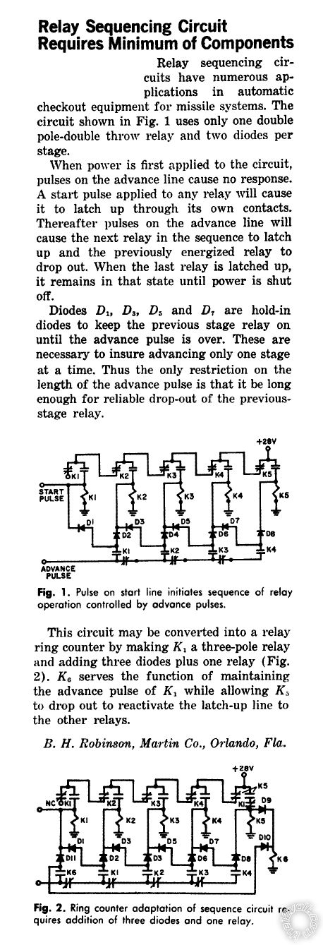
single pulse on/off latch relays -- posted image.
John DeRosa (Hotwaterwizard)
Stockton California
When in doubt, try it out !
oldspark 
Gold - Posts: 4,913
Gold spacespace
Joined: November 03, 2008
Location: Australia
Posted: March 21, 2012 at 11:09 PM / IP Logged  
Sounds like a good application for a CD4017 decade counter - a $3 16-pin chip.
To make it a "divide by n" counter, connect output n to the reset pin (#15).
EG for divide by 5, connect output #5 (pin #1) to pin #15.
That assumes that on power-up, output #0 (pin #3) drives the first relay, output #1 the 2nd, #2 the 3rd, #3 the 4th, & #4 the 5th relay.
The next switch push (aka clock) moves the output to #5 which rests it back to output #0 = relay #1.
You may not need the first relay.
I'd try to do it so the highest value resistance is soldered across the EMS input, then use the other relays to switch in different parallel resistors so that the combined parallel resistance equals the resistance you need (which is lower than the hardwiRED / soldered "default" resistor).
That minimises the chances of an open-circuit that might be detrimental.
trbolexis 
Member - Posts: 22
Member spacespace
Joined: February 24, 2012
Location: California, United States
Posted: May 21, 2012 at 10:26 PM / IP Logged  
AMAZING! Thank you for all the help and suggestions!
trbolexis 
Member - Posts: 22
Member spacespace
Joined: February 24, 2012
Location: California, United States
Posted: May 21, 2012 at 10:49 PM / IP Logged  
Could I use the outputs to directly drive particular restiances to the input device?
oldspark 
Gold - Posts: 4,913
Gold spacespace
Joined: November 03, 2008
Location: Australia
Posted: May 22, 2012 at 2:24 AM / IP Logged  
Der.... yes.
KPierson 
Platinum - Posts: 3,527
Platinum spaceThis member consistently provides reliable informationspace
Joined: April 14, 2005
Location: Ohio, United States
Posted: May 22, 2012 at 7:08 PM / IP Logged  
Have you checked the switches in the car yet? They typically are multiplexed to begin with which may add a layer of complexity to decoding the switch signal and then processing it.
Kevin Pierson
trbolexis 
Member - Posts: 22
Member spacespace
Joined: February 24, 2012
Location: California, United States
Posted: May 22, 2012 at 8:52 PM / IP Logged  
No. I have to an input to a digital input line on the ECU. It needs to vary from 0V to 5V because the ECU converts the input to ADC. I need the 5V broken down into 1V, 2V, 3V, 4V, 5V - each step will represent a breakpoint in the software to change a parameter.
I was considering using diodes to create the voltage drop, straight out of the CD4017B without need for any relays or otherwise. I was thinking 1B914 switching diodes because they actually have a forward voltage drop of 1V.
So Q1 of the chip would be 5V, Q2 would be 4V (after going through the diode, Q3 would be 3V (after going through 2 diodes), in theory of coarse.
Does this sound plausible?
Page of 4

  Printable version Printable version Post ReplyPost New Topic
You cannot post new topics in this forum
You cannot reply to topics in this forum
You cannot delete your posts in this forum
You cannot edit your posts in this forum
You cannot create polls in this forum
You cannot vote in polls in this forum

  •  
Search the12volt.com
Follow the12volt.com Follow the12volt.com on Facebook
Friday, March 29, 2024 • Copyright © 1999-2024 the12volt.com, All Rights Reserved Privacy Policy & Use of Cookies
Disclaimer: *All information on this site ( the12volt.com ) is provided "as is" without any warranty of any kind, either expressed or implied, including but not limited to fitness for a particular use. Any user assumes the entire risk as to the accuracy and use of this information. Please verify all wire colors and diagrams before applying any information.

Secured by Sectigo
the12volt.com spacer
Support the12volt.com
Top
the12volt.com spacer