the12volt.com spacer
icon

single pulse on/off latch relays


Post ReplyPost New Topic
< Prev Topic Next Topic >
trbolexis 
Member - Posts: 22
Member spacespace
Joined: February 24, 2012
Location: California, United States
Posted: May 25, 2012 at 9:05 PM / IP Logged  
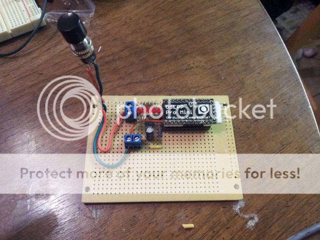
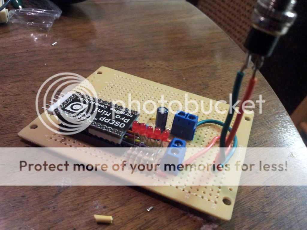
ITS ALIVE! WORKING PERFECTLY! Now I just have to pack it up nicely in a box.
Thanks EVERYONE for all input.
<iframe width="560" height="315" src="http://www.youtube.com/embed/OBY6p-cfoaE" frameallowfullscreen></iframe>
Here is the code for those interested: Please, do NOT use this code for commercial use, without my expressed consent.
[quote]#include <EEPROM.h>;
const int vOutpin = 3;
const int vInpin = 4;
const int led1 = 9;
const int led2 = 8;
const int led3 = 7;
const int led4 = 6;
const int led5 = 5;
const int address = 0;
int mode = 0;
int inputStatus;
void setup ()     {
Serial.begin(9600);
pinMode(vOutpin,OUTPUT);
pinMode(vInpin, INPUT);
pinMode(led1,OUTPUT);
pinMode(led2, OUTPUT);
pinMode(led3, OUTPUT);
pinMode(led4, OUTPUT);
pinMode(led5, OUTPUT);
}
void loop ()     {
mode = EEPROM.read(address);
if (mode < 1 && mode > 5) {
    EEPROM.write(address, 1);
}
if (mode == 1) {
    digitalWrite(led1, HIGH);
    analogWrite(vOutpin, 26);
    inputStatus = digitalRead(vInpin);
    Serial.println(inputStatus);
    if (inputStatus == HIGH) {     
      delay (750);
      //digitalWrite(led1, LOW);
      EEPROM.write(address, ++mode);
      return;
    return;
}
}
   if (mode == 2) {
    digitalWrite(led1, HIGH);
    digitalWrite(led2, HIGH);
    analogWrite(vOutpin, 77);
    inputStatus = digitalRead(vInpin);
    Serial.println(inputStatus);
    if (inputStatus == HIGH) {     
      delay (750);
      //digitalWrite(led2, LOW);
      EEPROM.write(address, ++mode);
      return;
    return;
}
}
   if (mode == 3) {
    digitalWrite(led1, HIGH);
    digitalWrite(led2, HIGH);
    digitalWrite(led3, HIGH);
    analogWrite(vOutpin, 128);
    inputStatus = digitalRead(vInpin);
    Serial.println(inputStatus);
    if (inputStatus == HIGH) {     
      delay (750);
      //digitalWrite(led3, LOW);
      EEPROM.write(address, ++mode);
      return;
    return;
}
}
   if (mode == 4) {
    digitalWrite(led1, HIGH);
    digitalWrite(led2, HIGH);
    digitalWrite(led3, HIGH);
    digitalWrite(led4, HIGH);
    analogWrite(vOutpin, 179);
    inputStatus = digitalRead(vInpin);
    Serial.println(inputStatus);
    if (inputStatus == HIGH) {     
      delay (1100);
      //digitalWrite(led4, LOW);
      EEPROM.write(address, ++mode);
      return;
    return;
}
}
   if (mode == 5) {
    digitalWrite(led1, HIGH);
    digitalWrite(led2, HIGH);
    digitalWrite(led3, HIGH);
    digitalWrite(led4, HIGH);
    digitalWrite(led5, HIGH);
    analogWrite(vOutpin, 230);
    inputStatus = digitalRead(vInpin);
    Serial.println(inputStatus);
    if (inputStatus == HIGH) {     
      delay (750);
      analogWrite(vOutpin, 26);
      digitalWrite(led1, LOW);
      delay (250);
      digitalWrite(led2, LOW);
      delay (250);
      digitalWrite(led3, LOW);
      delay (250);
      digitalWrite(led4, LOW);
      delay (250);
      digitalWrite(led5, LOW);
      delay (250);
      EEPROM.write(address, 1);
      return;
    return;
}
}
}
[/quote]
Thanks again!
Anthony
oldspark 
Gold - Posts: 4,913
Gold spacespace
Joined: November 03, 2008
Location: Australia
Posted: May 25, 2012 at 9:23 PM / IP Logged  
Typical!
WE effect the solution, and trbolexis clams the IP.
(But it is merely a "please", and I know the :consent" is really a disclaimer...)
And I'm jesting anyway.
Besides, IMO you have the worst part ahead of you - the physicals. The "circuitry" was always the easiest. It was the mounting and boxing etc that took the longest...
Good to see it working. And probably quicker than the discrete solution.
trbolexis 
Member - Posts: 22
Member spacespace
Joined: February 24, 2012
Location: California, United States
Posted: May 26, 2012 at 3:56 AM / IP Logged  
lol ... hey, is IS IP right? i mean, i do remeber writing the code :P
But you sir, please have free reign to use it as your own. I would have never gone down this path without your guidence, and for that i am greatly appreciative. :)
i have added all comments and refined the code dramatically. With debbuging inclusions and all (not that there is much to debug; more for verbose output to the Serial link for status changes/updates)
Again, i could not thank anyone who helped me with this solution enough. Where can i paypal someone some beer money? lol
trbolexis 
Member - Posts: 22
Member spacespace
Joined: February 24, 2012
Location: California, United States
Posted: May 26, 2012 at 3:59 AM / IP Logged  
single pulse on/off latch relays - Page 4 -- posted image. just need a box now!
trbolexis 
Member - Posts: 22
Member spacespace
Joined: February 24, 2012
Location: California, United States
Posted: May 26, 2012 at 4:02 AM / IP Logged  
single pulse on/off latch relays - Page 4 -- posted image.
oldspark 
Gold - Posts: 4,913
Gold spacespace
Joined: November 03, 2008
Location: Australia
Posted: May 26, 2012 at 4:54 AM / IP Logged  
IP as in Intellectual Property.
I was jesting, though I reckon I know what you mean.
If nothing else, it'd be nice to get some recognition.
As to "my" 5c** solution that was once posted on a site and now someone is "selling" that solution for AUD$35 (plus $7 postage) - well, I feel happier thinking of it as involving Australians with more cents than sense. [ ** 10c if redundancy or non-polarity/reversibility is desired. ]
Here in Aus your code above would be automatically "Copyrighted" to you having been written by you. But that law varies internationally (and sometimes with "software".)
At least it can't be Patented by anyone.
And then there's the usual issues - new or novel? Arduino is Open Source. You have posted it publicly.
Only a minor change may be needed, and YOU have to prosecute infringers...
I'm rapt because I stated feeling stupid that I suggested the 4017 because I felt the via-diode arrangement wasn't ideal, nor needing the "full" 5V output. (And I didn't do the math to calculate the resistor-matrix required to connect all outputs together.)
So then I commented on using a PIC which is so easy, yet so difficult.
But you made it so easy and so easy. Or so it looks anyhow.
The hard part is the programming (coding), though it's usually not such a big hurdle. Getting the correct RC delays for relay coils without chattering is probably more difficult.
And coding is a threshold thing that when crossed, enables so many things to be done. VIZ - dome- and puddle-light ramp-up and down dimmers, dash & LED dimmers, speed & RPM & temperature etc switches, voltage alarms, and far more complex stuff.
And though you are using an Arduino, if readers could picture that Arduino replaced with an 8-pin PIC chip that does the same thing... (Not that the PIC-08 would be switching all those LEDs, but it will vary the voltage that feeds your EFI boost control...)
Geez - maybe I should solder the 78L05 V-Regs & the programming resistors to my PICs. Then I might start coding... next year...
trbolexis 
Member - Posts: 22
Member spacespace
Joined: February 24, 2012
Location: California, United States
Posted: May 26, 2012 at 12:55 PM / IP Logged  
The PIC chip as you state is 100% ideal for a project like this. I could not agree more.
I was serious when i asked where i can paypal some beer, coffee, or tea money though :)
oldspark 
Gold - Posts: 4,913
Gold spacespace
Joined: November 03, 2008
Location: Australia
Posted: May 26, 2012 at 9:56 PM / IP Logged  
Thanks for the sentiment, but the sentiment is reward enough. (Maybe it helps that I found a job last week...?!)
I often find myself in "off world" positions...
EG - on the12volt I may argue against complex relay circuits - ie, IMO it's "easier" or better using electronics for logic.
On other "hi-tech" forums I argue in favor of relays (as opposed to solid-state relays or MOSFETs etc).
Nurds may consider relays too old-tech (I suppose just like wheels, bateries, telephones, and analog ear-canals) whilst relayers may consider a diode or logic gate too complex.
But IMO you have shown how easy it is.
I got the impression you were not "working familiar" with the PICs, yet within hours you had its code together.
We probably both have the advantage of some sort of programming & coding - and yes, that can be a hurdle or threshold experience.
I suspect some readers may get lost with the USB & serial stuff, but if they are on this forum, that's a minor detail. (USB or older serial mouse?)
As for coding, well at least coding "stops" at a certain point, whereas IMO electrical and circuit theory doesn't.
IE - there are a limited number of programming instructions and they have reasonably fixed behavior and outcomes. Brainstorming then uncovers different or more efficient ways of achieving the same or improved outcome.
Compare that to the electrical theory that even the "experienced" are not aware of. And then the (non!) arguments that arise as I recently found out (ie, people allegedly measuring VA for amplifiers or speakers instead of "real" power).
No wonder so many electronic things are being surpassed by programming!
Congrats on the outcome.
Maybe let us know if problems occur, or if you decide to improve the system... (EG - Arduino or PIC senses your repeated FAST throttling so it automatically increments boost since you have selected "auto" mode...)
Page of 4

Sorry, you can NOT post a reply.
This topic is closed.

  Printable version Printable version Post ReplyPost New Topic
You cannot post new topics in this forum
You cannot reply to topics in this forum
You cannot delete your posts in this forum
You cannot edit your posts in this forum
You cannot create polls in this forum
You cannot vote in polls in this forum

  •  
Search the12volt.com
Follow the12volt.com Follow the12volt.com on Facebook
Friday, March 29, 2024 • Copyright © 1999-2024 the12volt.com, All Rights Reserved Privacy Policy & Use of Cookies
Disclaimer: *All information on this site ( the12volt.com ) is provided "as is" without any warranty of any kind, either expressed or implied, including but not limited to fitness for a particular use. Any user assumes the entire risk as to the accuracy and use of this information. Please verify all wire colors and diagrams before applying any information.

Secured by Sectigo
the12volt.com spacer
Support the12volt.com
Top
the12volt.com spacer