the12volt.com spacer
icon

2001 honda civic ex


Post ReplyPost New Topic
< Prev Topic Next Topic >
littlenicky1 
Copper - Posts: 54
Copper spacespace
Joined: June 17, 2012
Location: California, United States
Posted: July 27, 2012 at 3:33 AM / IP Logged  
Cool I am going to go buy the new tester today. I learning how important testing because I am having to redo things by not taking the time first to double check things.
For the illuminated entry in my alarm manual it has a picture of the relay and one of the connections are the 87a to the 30 and the 30 to the ground. I am not sure if this is just an example of where the power goes or if I should connect the 87a to the 30 and then connect the 30 to the ground, which I might as well connect it all to the ground then. It also say connect to fused battery source but does not say how much the fuse should be. I am assuming it wants me to connect it to one of the wires that attach to the 12 volt constant that came with the alarm and reuse that fuse.
And to back track a little, I have been having trouble with this, in your diagram of the trunk pop just to clarify you connect the 85 that splits to 2 diodes, then one side goes to the button switch that came with my trunk pop solenoid, then to the ground, then back to the trunk pop solenoid, then back to the 30 relay?
And just a little info I figured out that I guess my factory alarm is gone. I was wiring into a the green plug and I realized that that should be plugged into my factory alarm. I do not see anything that that green plug should go to so that is my logical conclusion. I was wondering why it was just hanging there. As well, that ground and the clips were not of my doing. They were, as well, like that. I honestly tried to use the clips, but was hopeless unsuccessful and just feel like I am tearing up the wires, they do suck.
howie ll 
Pot Metal - Posts: 16,466
Pot Metal spacespace
Joined: January 09, 2007
Location: United Kingdom
Posted: July 27, 2012 at 4:23 AM / IP Logged  
You don't need illuminated entry, your dome light comes on automatically when the door is unlocked.
Are you adding a solenoid (actuator)for the trunk pop? If so:-
Alarm trunk release to 85 ground to switch to 85.
Diode both bands away from relay.
tommy... 
Gold - Posts: 1,901
Gold spacespace
Joined: December 10, 2004
Location: United States
Posted: July 27, 2012 at 9:11 AM / IP Logged  
The car is pre-wired, thats why the harness is there but no brain(thingy to plug the green harness into). It is just hanging there to make installs easier for us after-market people. They are really nice at Honda!2001 honda civic ex - Page 6 -- posted image.
M.E.C.P & First-Class
Go slow and drink lots of water...Procrastinators' Unite...Tomorrow!
howie ll 
Pot Metal - Posts: 16,466
Pot Metal spacespace
Joined: January 09, 2007
Location: United Kingdom
Posted: July 27, 2012 at 9:22 AM / IP Logged  
And that's where you pick up door, trunk and hood triggers, lights horn (?) power (for alarm not remote start) and ground.
littlenicky1 
Copper - Posts: 54
Copper spacespace
Joined: June 17, 2012
Location: California, United States
Posted: July 27, 2012 at 7:15 PM / IP Logged  
Ok for the 530t I found 11 wires that produce a circuit. 8 multi colored wires and 2 bigger black wires and 1 solid orange one. I believe that the orange one is the horn and the 2 black ones are ground right. The other ones I am assuming the other ones are the motor wires. They all read the same when I test them.
For the motion sensor how do I connect to ground and the alarm with the 4 pin out put that it comes with? The wire is a 4 pin to 4 pin wire? And when I will connect that to auxiliary 7 when I do figure out how to connect them right? Also, it says that it is a two stage alarm how do I wire the 1 and 2 parts of the alarm if I am just using the 1 auxiliary 7 output?
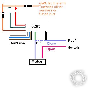
For the 529 the diagram you gave me it looks like you have two diodes on the same line facing different directions. I was wondering why.
Lookng forward to hearing from you thanks.
howie ll 
Pot Metal - Posts: 16,466
Pot Metal spacespace
Joined: January 09, 2007
Location: United Kingdom
Posted: July 28, 2012 at 2:08 AM / IP Logged  
WTH are you talking about? The only orange wire on a 530t is the thin trigger wire.
Could you re-link to the diagram showing the two diodes please, I must do 10 a week for different people.
littlenicky1 
Copper - Posts: 54
Copper spacespace
Joined: June 17, 2012
Location: California, United States
Posted: July 28, 2012 at 12:54 PM / IP Logged  
For THE WIRES IN MY CAR THAT SHOULD CONNECT TO the 530t I found 11 wires that produce a circuit. 8 multi colored wires and 2 bigger black wires and 1 solid orange one. I believe that the orange one is the horn and the 2 black ones are ground right. The other ones I am assuming the other ones are the motor wires. They all read the same when I test them. I need to find which one power the motor for each direction.
2001 honda civic ex - Page 6 -- posted image.
And again about the motion sensor I was confused how to connect the 4 pin to my car. For the motion sensor how do I connect to ground and the alarm with the 4 pin out put that it comes with? The wire is a 4 pin to 4 pin wire? And when I will connect that to auxiliary 7 when I do figure out how to connect them right? Also, it says that it is a two stage alarm how do I wire the 1 and 2 parts of the alarm if I am just using the 1 auxiliary 7 output? Thanks.
howie ll 
Pot Metal - Posts: 16,466
Pot Metal spacespace
Joined: January 09, 2007
Location: United Kingdom
Posted: July 28, 2012 at 1:24 PM / IP Logged  
Those two diodes in the picture are correct the other orange is going to the 530t.
Whatever is the A/Vox GWA wire goes to orange on the 530 and 429t but you diode separate as the picture.
The joined part goes to your A/Vox.
What's aux 7 on your A/Vox?
What's the GWA (ground when armed) on your A/Vox?
Someone who knows A/Vox alarms should chime in here please.
littlenicky1 
Copper - Posts: 54
Copper spacespace
Joined: June 17, 2012
Location: California, United States
Posted: July 28, 2012 at 4:36 PM / IP Logged  
Ok I got it. I think I am going to run all of my modules off the locks negative and positive right because when that arms I want everything else to close as well.
The auxiliary 7 output of the alarm give a 300 ma pulse. I am thinking now that I want to connect it now to the locking wire because I want it to arm with the locks, windows closing and sunroof closing at the same time right? My big question about that is how I should connect the wires because the end is a 4 pin with the wires all connected. I would rather not cut the wires so I was wondering if there is another way to do that.
littlenicky1 
Copper - Posts: 54
Copper spacespace
Joined: June 17, 2012
Location: California, United States
Posted: July 30, 2012 at 3:25 AM / IP Logged  
I am having the hardest time figuring out how to test to find out which of the wires in my car turn each different motor and which way as well they turn to my windows and sun roof. When I test the wires coming from the switch from the door handle I get all the same drop in voltage and polarity when I switch one of the switches. I am unable to isolate which wire does what function to the windows and sun roof. What am I doing wrong to find this out? I believe it is either the wrong wires or the wrong way of testing. Thanks.
Page of 6

Sorry, you can NOT post a reply.
This topic is closed.

  Printable version Printable version Post ReplyPost New Topic
You cannot post new topics in this forum
You cannot reply to topics in this forum
You cannot delete your posts in this forum
You cannot edit your posts in this forum
You cannot create polls in this forum
You cannot vote in polls in this forum

  •  
Search the12volt.com
Follow the12volt.com Follow the12volt.com on Facebook
Tuesday, May 14, 2024 • Copyright © 1999-2024 the12volt.com, All Rights Reserved Privacy Policy & Use of Cookies
Disclaimer: *All information on this site ( the12volt.com ) is provided "as is" without any warranty of any kind, either expressed or implied, including but not limited to fitness for a particular use. Any user assumes the entire risk as to the accuracy and use of this information. Please verify all wire colors and diagrams before applying any information.

Secured by Sectigo
the12volt.com spacer
Support the12volt.com
Top
the12volt.com spacer