the12volt.com spacer
icon

2001 honda civic ex


Post ReplyPost New Topic
< Prev Topic Next Topic >
littlenicky1 
Copper - Posts: 54
Copper spacespace
Joined: June 17, 2012
Location: California, United States
Posted: July 22, 2012 at 5:27 PM / IP Logged  
Thanks I got that figured out. I had a question about if I use the Audiovox SS6900 alarm's blue ignition 1 output from the 6 pin power harness or the black and yellow wire 12 volt alarm by-pass output or do I use both of them?
Another question, for my tack monitor set up my wire diagram tells me to connect the the alarms GREEN/ orange wire to the blue wire to the left of the battery. I found a similar looking wire behind the fuse box. Am I able to tap into that rather than to the blue wire by the battery?
As well, I believe that I have a factory installed remote unlock and locking only. When wiring the 4 auxiliary harness harness what outputs would I be connecting them to?
Also, one final question what output do I connect the 530t's and do I connect both on the same channel or use 2 channels? Thanks like always for your help and hope to hear from you soon.
howie ll 
Pot Metal - Posts: 16,466
Pot Metal spacespace
Joined: January 09, 2007
Location: United Kingdom
Posted: July 23, 2012 at 1:23 AM / IP Logged  
I have to state that A/Vox product isn't available in Europe and I've never installed one.
However from looking at the manual, blue to car's BLACK / YELLOW.
Is there a factory alarm, cig. pack sized module with a white plug bolted outboard of t5he steering column?
I'm guessing here because I've only done UK build right hand drive, we have a pocket to the right on the driver's side lower dash, it's above and behind it.
Yellow/black to the wire that goes to 12v+ when ignition is turned on.
That blue/wire also goes to the tach in the instrument panel.
Under hood, left hand side, (again it's the opposite here), should be behind the suspension strut, joined to the main loom with blue tape, ends as one wire going to a double plug,dark grey? Also to the coil pack depending on year and model.
howie ll 
Pot Metal - Posts: 16,466
Pot Metal spacespace
Joined: January 09, 2007
Location: United Kingdom
Posted: July 23, 2012 at 2:29 AM / IP Logged  
Which 4 pin aux harness?
I looked at the install manual and couldn't find a GWA (ground whilst armed) I think I'm going mad!
Any way you could use the GREEN/ black channel 4 as raise (leave at 20 seconds default) and blue/black channel 5 as vent/lower.
Alternatively read the instructions on the 530t, they list a way of doing it off the lock wire.
Alternate 2, a latching relay from the lock wire.
littlenicky1 
Copper - Posts: 54
Copper spacespace
Joined: June 17, 2012
Location: California, United States
Posted: July 23, 2012 at 11:05 PM / IP Logged  
Thank you for the new help. For the 530t what wire do I connect to the RED / white h2/3 wire? It says the auxiliary input on the 530t to the (-) output to the alarm but I am not sure which one that is. As well for the added relay where is the (-) lock pulse from the security system. This features makes the windows go up when I lock the car right? I believe I am just going to follow the instructions from the 530t, I believe that is going to be the easiest with the most features.
With the locks I am having a hard time figuring out what diagram I should use with my car? The manual for my car has a few different ones. Does it mater or does on allow more features?
For the 4 port auxiliary port it was this one I did not know what is was used for. I was also confused on what ground wire you were looking for?
WIRING THE 4 PIN AUXILIARY OUTPUT HARNESS:
The auxiliary 4 pin connector provides low current outputs to control various functions in the vehicle during
different stages of the Remote Start unit's operation. Understanding these outputs and the time in which they
occur will allow you to determine if they are needed for the particular vehicle you are working on as well as
how to use them.
BLACK w/ BLUE TRACE WIRE: Pulsed Ground Output Before Start
The Black w/ Blue Trace wire will provide a 1 second, 300 mA pulsed ground output 1.5 second before the
remote start unit activates as well as when the transmitter is used to disarm the system. Typical use for this
output would be to disarm a factory theft deterrent system to prevent false triggering of the factory alarm
when the remote start unit engages or when the transmitter is used to unlock the doors.
BLACK w/ LIGHT GREEN TRACE WIRE: Pulsed Ground Output After Start
The Black w/ Light Green Trace wire will provide a 1 second 300mA pulsed ground output after the vehicle is
started under control of the remote start unit. Typically this wire will be used to re-lock the vehicle doors if the
doors unlock automatically when the factory anti-theft system is disarmed.
BLACK w/ RED TRACE WIRE: Pulsed Ground Output After Shutdown
The Black w/ Red Trace wire will provide a 1 second, 300 mA pulsed ground output after the remote start unit
shuts down. This output will occur regardless of whether the circuit times out or is manually terminated.
Typically this output will be used to re-lock the vehicle doors if the doors unlock automatically when the
ignition circuit transitions to off.
BLACK w/ YELLOW TRACE WIRE: Ground Output During Start (Crank)
The Black w/ Yellow Trace wire will provide a 300 mA ground output while the starter output of the remote
start unit is active. This output can be used to activate the Crank Low/Bulb Test wire found in some GM
vehicles. This wire is also referred to as the ECM wake up wire in some Chrysler vehicles.
Note: The outputs above are low current outputs and must be used with a relay if the circuit's requirement
is more than 300 mA.
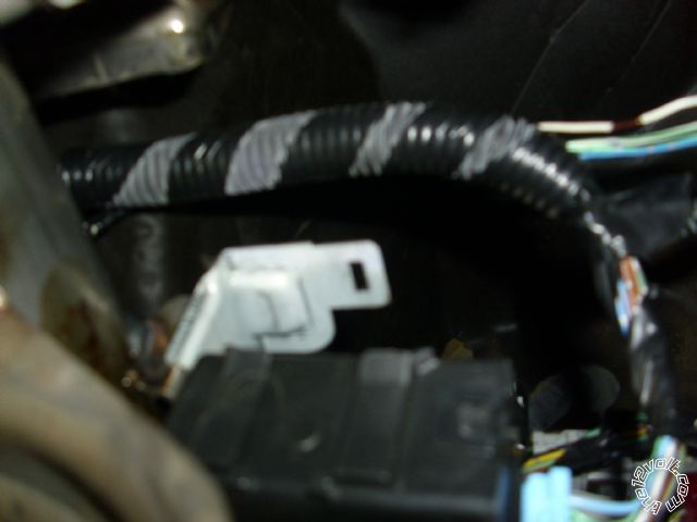
I called the dealership and he said I should have a factory alarm but when I looked for it I could not find it. There was a cig. sized box but it was for the cruse control. There is an empty slot next to it where I think it should be. See pic. So I am not sure at this point. Is there anyway else I can confirm that?
The alarm is coming together thanks to your help. When should I want to test things to make sure they work right? When I am completely wired or when I finish a parts of it?
2001 honda civic ex - Page 5 -- posted image.
howie ll 
Pot Metal - Posts: 16,466
Pot Metal spacespace
Joined: January 09, 2007
Location: United Kingdom
Posted: July 24, 2012 at 1:24 AM / IP Logged  
Is the RED / white H2 the GWA wire?
Then that's the wire that goes to the orange and ORANGE / black on the 530t.
And the alarm's blue/black to grey and grey/black.
The locking is simple, find the vehicle's lock and unlock wires, fusebox or a white plug in DKP using your DMM*, N.B. won't work with key in ignition and throw over the latch at the back of the door.
Red to WHITE/ green for lock and and green to WHITE/ blue for unlock, diode the wires, 1N4004, bands to SS6900.
As for the alarm, open a back window, remote lock the car, wait about 1 minute then reach in and open a back door. If nothing happens no alarm.
That photo is too blurry to see anything. Is there an unused white plug and can you photograph it?
Apparently it's above the DKP, not where I said.
The 4 pin plug isn't needed, but you will need to diode split your GWR wire to the key sense and by-pass if needed.
Look for 2 items in the Downloads/Manuals section, shows how to by-pass the factory alarm (Civic 1) and the vehicle fusebox, (Civic 2).
*You really don't need a DMM for this car, a good incandescent (filament) bulb tester such as a Snap-On CT-45 is adequate and faster for this car, the DMM is only required to test tach.
howie ll 
Pot Metal - Posts: 16,466
Pot Metal spacespace
Joined: January 09, 2007
Location: United Kingdom
Posted: July 24, 2012 at 2:17 AM / IP Logged  
Errata, look in the Downloads/Manuals section for Civic Fusebox only.
Here's a way to disable the factory alarm during remote lock:- honda_keysense_activation.bmp
littlenicky1 
Copper - Posts: 54
Copper spacespace
Joined: June 17, 2012
Location: California, United States
Posted: July 24, 2012 at 11:59 AM / IP Logged  
Ok thanks doesn’t seem too difficult. The 530t says the RED / white H2 wire is the auxiliary input and it says to connect to a (-) validity channel of the output alarm and I do not believe that would be a ground right? And you next sentence about what to use the alarm’s blue/black is it for is it the light blue/black or the dark blue/black? I understand that I connect that to the grey wire on the 530t but I wasn’t sure what to do with the grey/black wire. I did not know if I should wire all 3 together? Also, I forget, I want to diode the negative GWA wire right? And I have been soldering them on that’s the best way to attach them right?
And What does N.B. stand for?
howie ll 
Pot Metal - Posts: 16,466
Pot Metal spacespace
Joined: January 09, 2007
Location: United Kingdom
Posted: July 24, 2012 at 12:14 PM / IP Logged  
RED / white is the 530t? I thought it was the alarm2001 honda civic ex - Page 5 -- posted image.
That goes to an aux output you care to choose set to pulse (momentary).
Such as blue/black.
Orange goes to your ground when armed output or if you want to raise the windows at any time use the GREEN/ black as timed set 20 seconds.
But then I've already mentioned this haven't I? That's what's meant by N.B. Nota bene, Latin for NOTE WELL.
As for the 530t grey, it's there to connect to a relay during window raise to disable shock etc. sensors during window raise/lower if required.
(-) aux simply means GROUND when activated answering your other question.
As for light/blue and dark blue your looking at the alarm's aux outputs, I don't have an install manual so you tell me.
littlenicky1 
Copper - Posts: 54
Copper spacespace
Joined: June 17, 2012
Location: California, United States
Posted: July 25, 2012 at 12:50 AM / IP Logged  
Ok for the window module do you know what colors that I need to connect for the motor wires in my honda civic? I cannot find a diagram for it and those wires are not on the fuse box diagram you showed me earlier. There are 6 or 8 wires I am looking for. I am and not sure because in the manual it says that the back windows run on the same circuit but I can roll them up individually so I would think that they would be different.
Also, I had a little trouble deciding what way I needed to wire the locks I know my system is negative but there is still 2 ways of doing it. For the locks it says I need relays with it.(reference page 13 of the manual) Does using a diode take the place of the 5 pin relay? If so then when do you use relays over diodes? As always any and all help is greatly appreciated. 2001 honda civic ex - Page 5 -- posted image.
2001 honda civic ex - Page 5 -- posted image.2001 honda civic ex - Page 5 -- posted image.
2001 honda civic ex - Page 5 -- posted image.
http://audiovox2.info/docs/common/SS6900/SS6900_IM.pdf2001 honda civic ex - Page 5 -- posted image. 2001 honda civic ex - Page 5 -- posted image. 2001 honda civic ex - Page 5 -- posted image.
howie ll 
Pot Metal - Posts: 16,466
Pot Metal spacespace
Joined: January 09, 2007
Location: United Kingdom
Posted: July 25, 2012 at 3:08 AM / IP Logged  
You open up each door panel and test the two wires as they go to the motor. You will need to do that anyway to wire the 530ts properly.
Diodes are needed because of the type of lock outputs they are low neg, I've usually picked them up at the long white plug above the DKP. Shown in both your pictures, the smaller plug with the thinner wires.
Of course back and fronts are the same circuit...The power and ground.
You are doing the usual DIY trick of over doing the analysis and not enough testing.
Throw away the DMM and use a test light such as a Snap-On CT 45.
Also you are about to get into serious non connection, vibration and corrosion problems using those red plastic IDC connectors. Remove and solder.
That blue ring held by a tap-tight screw below the plugs? Also a no-no. Use the existing M6 bolts in the kickwell or any where else making sure you scrape away the paint under the bolt.
Page of 6

  Printable version Printable version Post ReplyPost New Topic
You cannot post new topics in this forum
You cannot reply to topics in this forum
You cannot delete your posts in this forum
You cannot edit your posts in this forum
You cannot create polls in this forum
You cannot vote in polls in this forum

  •  
Search the12volt.com
Follow the12volt.com Follow the12volt.com on Facebook
Wednesday, May 15, 2024 • Copyright © 1999-2024 the12volt.com, All Rights Reserved Privacy Policy & Use of Cookies
Disclaimer: *All information on this site ( the12volt.com ) is provided "as is" without any warranty of any kind, either expressed or implied, including but not limited to fitness for a particular use. Any user assumes the entire risk as to the accuracy and use of this information. Please verify all wire colors and diagrams before applying any information.

Secured by Sectigo
the12volt.com spacer
Support the12volt.com
Top
the12volt.com spacer