the12volt.com spacer
icon

basic l.e.d. wiring


Post ReplyPost New Topic
< Prev Topic Next Topic >
corrollaman 
Member - Posts: 38
Member spaceThis member has made a donation to the12volt.com. Click here for more info.spacespace
Joined: November 17, 2009
Location: Kansas, United States
Posted: July 23, 2012 at 2:40 PM / IP Logged  
In the big final picture I would like the brake light to blink really fast a few times in a given 1 or 2 seconds.. then full on when i apply the brake.. only mentioning this since I will inevitabley be doing this but that might change the reasoning on what path to take for the best outcome.
ajm
corrollaman 
Member - Posts: 38
Member spaceThis member has made a donation to the12volt.com. Click here for more info.spacespace
Joined: November 17, 2009
Location: Kansas, United States
Posted: July 23, 2012 at 3:08 PM / IP Logged  

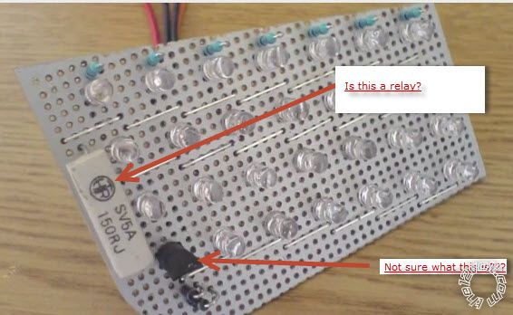
This is a shot from the example I am using as a reference.

He doesnt show a relay.. but obviously he is using something outside of what the schematic is he put together.....???

basic l.e.d. wiring - Page 2 -- posted image.

ajm
corrollaman 
Member - Posts: 38
Member spaceThis member has made a donation to the12volt.com. Click here for more info.spacespace
Joined: November 17, 2009
Location: Kansas, United States
Posted: July 23, 2012 at 3:22 PM / IP Logged  
Scratch that .. "is this a relay" its a resistor.. and im not sure why that is in place...
ajm
KPierson 
Platinum - Posts: 3,527
Platinum spaceThis member consistently provides reliable informationspace
Joined: April 14, 2005
Location: Ohio, United States
Posted: July 23, 2012 at 3:32 PM / IP Logged  
The white thing looks like a resistor to me (3 or 5w or so). The black thing looks like either a transistor or a voltage regulator with electrical tape over the top of it.
Kevin Pierson
oldspark 
Gold - Posts: 4,913
Gold spacespace
Joined: November 03, 2008
Location: Australia
Posted: July 23, 2012 at 8:24 PM / IP Logged  
That diagram is equivalent to what I said in my last reply but with each string having a dim resistor to +12V into the lower bright resistor and into the LEDs. The relay connects +12V to the junction of the resistors. But that diagram shows the resistors in parallel which means the dim resistor also supplies the bright current in bright mode (ie, the bright resistor is larger than it need be.)
oldspark wrote:
Ideally each string should have its own resistors, but that makes the dim bypassing difficult...
Yeah - I don't know why I wrote that. I'll put it down to being early morning, pre-coffee & pre-shower. (You need to develop reasonable excuses when dealing with electronics. Take the rap, but with dignity. IOW, your excuses will have to be better than mine.)
Apart from the parallel resistor topology of the circuit you posted, it's been done by an amateur. I pick that from the resistor values that do not have to be that specific (preferred values should always be acceptable - eg, 270R & 820R in that case; where R means Ohms).    
Also those diodes should be unnecessary in a 12V application. (If the LEDs can handle their forward voltage, then they shouldn't need ordinary diodes as they might for AC solutions.)
And I don't know why the single big resistor in the dim supply. Maybe it's to allow easy variance of the dim level? (But then ensure the dims are bight enough, and add that resistor later if needed.)     
And yes, the big white thing is a resistor, 150 Ohms (150R) of probably 5W rating (5A??).
I have no idea what the black thing is. Limped resistors maybe (which is bad), or a tap/connector, some type of fuse, surely not a thermal sensor?. It's small to be a voltage regulator that powers the LEDs. It might be a transistor for extra control...
I'd suggest my series method of connecting the resistors instead of its parallel method, though that depends on your flashing brake lights.
Do you want your brakes to flash between bight and dim(tail), or bright and off (dark)?
Also, the flashing may suggest a PICAXE. That's easier than the adding the timing circuits required.
Assuming such flashing is not illegal, it can be speed related (less flashes at low speed) and it is usually limited to no more than 3 flashes.
A PICAXE can do all the dimming required (using PWM) as well as be programmed with the relevant flash code - and even feed with a speed signal.
The PICAXE would have 2 or 3 inputs - tail, brake and optional speed. One output to a MOSFET ($3) that connects all LED strings to GND and is then PWMd or modulated for dim and flashing. No relays, and each string need only have the one "bright" resistor (all connected to +12V or IGN +12V etc).
As an example of how simple(?) it can be, see mp3car's Controlling back lights directly?.
That is similar to your project and goes through various suggestions before the OP decided on the PIC solution (see page 3).
POST EDIT: I just checked that mp3car thread and it does not have the last replies that I expected. Maybe the OP deleted the relevant replies & coding else I picked the wrong thread.
corrollaman 
Member - Posts: 38
Member spaceThis member has made a donation to the12volt.com. Click here for more info.spacespace
Joined: November 17, 2009
Location: Kansas, United States
Posted: July 23, 2012 at 10:08 PM / IP Logged  
A pic axe, that's a little extreme don't you think? hehe
If you look at this link, http://petemills.blogspot.ca/2012/04/tenty-led-brake-lights.html, I would like a pulse of brake light that is similar to Peters. I believe it's legal to do up to three pulses without being classified as a flasher, which is illegal in the states.(and not someone in a trench coat, kind of flasher)
I'm on board with the PICAXE idea.. being green behind the ears, but enjoying the hell out of learning about electronics makes that suggestion an easy Yes. I read through Peters entire guide/setup and when i did further research i was going to have to buy a software application and some kind of PIC programmer etc.. (wasn't too keen on the idea of spending even more money)
I gather from what you describe it wouldn't take much to get the PICAXE, the software is free, and from what I read on that Ch. 3 all i need is a serial cable, which i have some at the office. I wasn't sure what a MOSFET was.. but after I googled it.. its a transistor.. so now all I need to do is figure out how all this comes together. More research.. :-D
So far I am already on board with doing 48 LED's in a an array of 3 per string.(based off of a LED array calculator)
I have checked the voltage from where I am getting power and it sits around 13.2-14.4 depending on if i am really giving it the gas.. I am wondering if I should put a voltage regulator on it or not.. and what voltage would i use for my calculations. I am thinking when this is all put together I may have to adjust my Resistance a few times so as not to blind the people behind me.. hehe I have also wondered about using a capacitor and a voltage regulator.. keeping in mind that I want this perfect so I don't destroy the leds and they outlast me.
Okay I am done rambling on and on....
Once I have enough information, and sleep. hehe I will put together a drawing of all this.... my dreams have been full of leds.. hehe
(LEDS: Red 8mm .5 watt 3.4-3.6V, 20mA Vf, 100Kmcd)
ajm
oldspark 
Gold - Posts: 4,913
Gold spacespace
Joined: November 03, 2008
Location: Australia
Posted: July 23, 2012 at 11:59 PM / IP Logged  
Phew - "a little extreme for a picaxe" and then you link to an ATtiny!
Nah - pick any axe when needed. (ha ha)
And the ATmega stuff is good too (ie, Arduino).
Not that I'm that familiar with ATtiny requirements, but the PICAXE only requires a 5V regulated supply, and 2 resistors that are required for programming. They have very low power consumption, hence small 100mA V-Regs are usually fine. (Good too for power conservative projects - solar & battery etc.)
You then add whatever other components are needed, like automotive voltage protection (for the VReg = eg, reverse spike diodes, MOV or +ve spike limiters assuming 100V etc spikes), I/O (input/output) connectors and their filter or buffer circuits - eg, RC filter for inputs; resistor and MOSFET for outputs.
The MOSFET is like a transistor but is controlled by voltage instead of current. (Transistors have a gain - aka β or Beta - which is the (max) ratio of output-current :to: Base (input) current.)
A FET only takes nA (nano-Amps) thru its Gate (equivalent to a transistor's Base) instead of the several mA etc by a transistor Base.
A FET requires typically ~4V-5V above its Source (equiv to transistor's Emitter) to turn it fully on. (+ve for N-channel, P-chanel requires 4-5V BELOW the Source voltage).
A FET's (MOSFET's) output is usually quoted as resistance, ie, RDSon (Resistance of Drain to Source when (fully) ON).
MOSFETs typically have well under 1R (1Ω) on resistance and often measured in mR (mΩ).
It's easiest using an N-channel MOSFET where its Gate needs to be (say) +5V higher than the Source to turn it on.
That's great because you'll probably want to use GND switching. (Many "control circuits use GND switching - eg, car alarms, immobilisers, computers, ignition coils, injectors. It's also known as "Open Collector Output" which means that it is grounded when on, and "floating" when off. I've written about that on the12volt as well as elsewhere, but there are lots of other references.)
The reason for GND or Open-Collector switching is that it doesn't mater what voltage the switched component is.
EG - your 5V uPC (PIC, AT, whatever) can't supply (say) +12V without difficulty, so instead have it turn on a switch that grounds the target device (LEDs).
It does assume that you can isolate the LEDs from GND - ie, normal bulbs are often grounded thru their holder and the chassis/body. But I suspect that is not an issue in your case.
I wonder about your red LED voltage of ~3.6V, but I'll check up on that. Reds are usually ~2V but maybe these high output (and high Wattage - 0.5W) LEDs are different. Maybe they are whites with a red lens?
Normally I'd suggest 4 maybe 5 series red LEDs for 12V automotive systems, whereas it's usually only ~3 for whites (ie, ~3.5V each).   
That's allowing for voltage dips below the usually battery voltage of ~12.6V (maybe down to 12V or 11V when idling with headlights on etc).
Of course it must also handle the normal long-term system voltage of 14.2V to (max) 14.4V, and maybe the odd 14.5-15V or 16V (after cranking etc). But that's where LED characteristics often tolerate such "over-voltages" - ie, if designed for your norm of (say) 14.2V but has short duration over-voltages of 15V - 16V (ie, up to 30 seconds?).
For 3.6V LEDs, I'd use no more than 3 in series, hence 3x3.6 = 10.8V which provides enough margin for the resistor drop and any MOSFET drop.
Assuming 14.4V, that means 14.4-10.8V = 3.6V across the resistor. (Hence I might use 4 series LEDs, but many seem to prefer a resistor...)
Hence from V=IR (Ohm's Law), R = V/I = 3.6V/20ma = 180R. (Wow - bang on a preferred value. The other nearest are 220R & 150R. I might be tempted to use 150R is the FET adds a reasonable voltage drop...)
It's wattage: 3.6V x 0.2A = 0.072W, hence a 1/8W (0.125W) or 1/4W etc. Traditionally I'd use a 1/2W resistor as these use to be physically more robust, but last time I bought, 1/2W resistors were the same size as the old 1/4W resistors. Get whichever is cheapest or common and suits your design.
(Or Wattage using a combined V=IR & P=VI formula, namely P=VV/R = IIR => 3.6 x 3.6 / 180 = 0.072W or .02A x .02A x 180 = 0.072W. See - it all agrees, otherwise I've made an error somewhere...)
Hence n-number of strings comprising 3 LEDs and a 180R resistor per string.
Total max current is 20mA times the number of strings (ie, n x 20mA or n x 0.02A).
The add the required dim resistor per string, OR sove a MOSFET between the -ve ends and 0v (GND) and have a uPC PWM for dim tails, fully on for brake, and modulating (flashing) for flashing stops.
That modulation could be between fully on (brakes) and PWM'd tails, or fully on and off.
Tails too dim or bright? Change the programmed PWM value.
Want to increase flash rate with speed? Program the speed sensor adjust the flash frequency.
Want to change the number of flashes or even the on-off ratio (duty cycle) - maybe with varying speed? You guessed it, just change the program.
Yes, these uPCs have a bit of an initial learning curve, but then almost anything can be done without the need to add or change resistors, capacitors, etc.
BTW - look at the PICAXE 08 series (8 pin), often designated by a PIC12Fxxx number depending on model.
The later 08M is quite good but the latest 08M2 has more improvements. Both have enough program space and features for what you want.
Incidentally, I'm looking at getting preferably the SMD (surface mount) AXE230 kit, though DIL [Dual In-Line (pins - ie, chips with leads/pins)] like the RKP08 (RKP08c) are also available.
Google the above numbers... Unfortunately some of the kit descriptions are vague - ie, does the AXE230 come with the 08M or 08M2 already soldered in place?
Probably the DIL version is best for testing etc. Production may call for the much smaller SMD version. (Isn't it ridiculous when the 2 programming resistors are as large as the entire PIC08 with it's thousands of transistors etc?)
Just another short reply...
PS - to clarify if not already read or implicit, a voltage regulator should not be necessary for the LEDs. (But the uPC. PIC, AT, whatever, will need its voltage regulator.)
Though many seem to use voltage regulators or current limiting devices (a single limiter for several strings - if one string fails, what's the point??!) and write how successfully they have operated, I have yet to see any of them say how they operate whereas non-regulated circuits didn't. IE - they are usually those that think LEDs have exacting voltage or current criterion, hence they travel down the complicated and more expensive overkill path.
Look at OEM vehicle LED lighting. Nothing more than a resistor in series with LEDs. No other form of current (or voltage) regulation. Yet they seem to last ages. (Tell me if I'm wrong.) My only failure was a broken wire within an after-market LED stop/tail "bulb".
corrollaman 
Member - Posts: 38
Member spaceThis member has made a donation to the12volt.com. Click here for more info.spacespace
Joined: November 17, 2009
Location: Kansas, United States
Posted: July 24, 2012 at 8:22 AM / IP Logged  

Awesome. Thank You soooo much.. I am sure I will have more questions, but it is going to take me a while to digest all this in between my 1 yr. old and my travel. Once I get everything together I need I will end up putting together the schematics and passing them on to you.

Again, much Thanks!!

ajm
corrollaman 
Member - Posts: 38
Member spaceThis member has made a donation to the12volt.com. Click here for more info.spacespace
Joined: November 17, 2009
Location: Kansas, United States
Posted: July 24, 2012 at 10:49 AM / IP Logged  

"The reason for GND or Open-Collector switching is that it doesn't mater what voltage the switched component is.

EG - your 5V uPC (PIC, AT, whatever) can't supply (say) +12V without difficulty, so instead have it turn on a switch that grounds the target device (LEDs).
It does assume that you can isolate the LEDs from GND - ie, normal bulbs are often grounded thru their holder and the chassis/body. But I suspect that is not an issue in your case. "

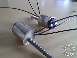
I will be wiring this directly to a bulb which is grounded.(will have 3 wires coming out of it)  This way I dont have to get into any of the wiring harness.

basic l.e.d. wiring - Page 2 -- posted image.
"Assuming 14.4V, that means 14.4-10.8V = 3.6V across the resistor. (Hence I might use 4 series LEDs, but many seem to prefer a resistor...)"
-As for the led's in a series without a resistor... if you were doing this project would you go without the resistor and just do 4 in a series? I wonder what the pro's and con's are of using or not using the resistor?
"I wonder about your red LED voltage of ~3.6V, but I'll check up on that. Reds are usually ~2V but maybe these high output (and high Wattage - 0.5W) LEDs are different. Maybe they are whites with a red lens?"
-->LEDs i bought( http://www./itm/200762934769?ru=http%3A%2F%2Fwww.%2Fsch%2Fi.html%3F_sacat%3D0%26_nkw%3D200762934769%26_rdc%3D1)

I cant think of anything else..

ajm
oldspark 
Gold - Posts: 4,913
Gold spacespace
Joined: November 03, 2008
Location: Australia
Posted: July 25, 2012 at 3:29 AM / IP Logged  
eBay links don't work. But I found it using the item number.
Reds should always be ~2V. It's the chemicals involved that determine the color, and the elements/chemicals determine the voltage. That's how I recall it anyhow.
They claim it's a clear lens. Maybe the lens is clear but there's a filter underneath? Or maybe there are 3.6V reds. I doubt that they'd use 2 reds in series.
Incidentally, I looked at wiki's LED_circuit page (which is to be deleted and replaced by its Light-emitting_diode page), and John Hewes's Electronics Club led page.
They confirm the bigger electrode is the -ve (Cathode), and I now have a new rule - the flat side if the LED-base is a flat line, ie, a -ve, and ergo that's the -ve end. (But I always look thru the LED to check.)
They have nothing about reds being >3V.
But I like how John Hewes's led page has a section "Avoid connecting LEDs in parallel!". I'll quote that next time someone argues - especially about using a single current limiter for multiple LED strings.
If I did this project would I go without the resistor and just use 4 in a series? (Assuming white etc or up to ~3.6V each.)
Probably yes.
But that's a combination of factors, eg:
- I know some that do the same and have not complained - eg, 6 to 8 reds, or 4 whites, etc. (I believe some on the12volt have.)
- I'm prepared to lose a few in my error(?) and then retrofit a resistor i place of one of the LEDs, or rewire appropriately.
BUT, if I am using PWM to modulate the brightness, I'd merely reduce the maximum duty cycle - ie, from 100% to 90% or 80% etc.
Note that the LED is a current device. It is over-current that kills them, not over-voltage. (And it is current that controls them - eg, their brightness - they are not "linear" devices like bulbs where current is (closely) proportional to voltage, ie, V=IR.)
What I am saying is that the voltage is essentially irrelevant for a LED. The voltage is merely selected to provide the appropriate current for it.
But in that, it must be understood that there is a relationship between V & I (it's a donkey & cart or chicken & egg thing) and that the voltage cannot be so high as to puncture the LED - ie, semi-conductor breakdown - by exceeding PIV or Vf-max limits, ie Peak Inverse (reverse) Voltage or max Forward Voltage.
[ I think that's why 110-230VAC LED lights break down so much. They seem to use mere diode rectification with highish light output. That means highish RMS (ie, "average") current/voltage, but the peak voltage will be ~1.4 times the RMS voltage, hence I suspect premature failure. I don't know why they don't use an SMPS circuit (or full-bridge rectification and filtering though the caps are an issue) and convert the AC to a steady DC. Mind you, it could also be the long series strings involved - lose one and lose them all (immediately if open-circuit; eventually if short-circuit failures), but then use an SMPS to convert to lower voltage parallel strings. ]
Ooops - did I digress yet again?
Anyhow, I assume you have a DMM (multimeter).
Test with whatever voltage and resistor and measure the current.
Ideally a 2nd DMM/voltmeter to measure the LED voltages, though using a single DMM should be ok (the current measurement inserts a resistance, but that should be negligible, and voltage readings will not effect the circuit).
Besides, knowing the resistance and its current, you can calculate its voltage drop accurately (V=IR) and hence calculate the voltage across the LED(s) - ie, Vs - Vr (Supply voltage minus Resistor voltage).
An initial test with series LEDs should be to see how similar their voltages are. They will vary a bit... (Even LEDs manufactured o the same silicon die vary in their voltage for a given current - unless they have solved that issue in a past few years.)
You might even want to burn a few to see what current blows them almost immediately. (Note that you must watch the DMM current reading just before failure. It will drop to zero as soon as they/it blows - unless it blows in short-circuit mode which is unlikely (for over-current) but that short-cct measurement is useless anyway.)
That might give you a bit of confidence that they can tolerate some extremes.
But be aware that stressing may not lead to immediate failure - it may just decrease their lifespan. Also many components fail on over-current for thermal reasons and they may take a while to warm up (thermal inertia), though LEDs generally have little thermal inertia and blow quickly.
Make sure you have the right topology before you construct the final. Having to rewire a (say) 24-LED light from 6 strings of 4 to 8 strings of 3 is a PITA!
Changing of resistors or adding a PWM won't be as painful.
Remember too that the LEDs have to be bright enough with the car's lowest voltage. However you should find that dropping from 14.4V to (say) 11V or 9V does not have a major effect. IE - the voltage might drop ~35% to 9V but the LED intensity might only drop 10% - 20% etc.
Page of 5

  Printable version Printable version Post ReplyPost New Topic
You cannot post new topics in this forum
You cannot reply to topics in this forum
You cannot delete your posts in this forum
You cannot edit your posts in this forum
You cannot create polls in this forum
You cannot vote in polls in this forum

  •  
Search the12volt.com
Follow the12volt.com Follow the12volt.com on Facebook
Monday, May 6, 2024 • Copyright © 1999-2024 the12volt.com, All Rights Reserved Privacy Policy & Use of Cookies
Disclaimer: *All information on this site ( the12volt.com ) is provided "as is" without any warranty of any kind, either expressed or implied, including but not limited to fitness for a particular use. Any user assumes the entire risk as to the accuracy and use of this information. Please verify all wire colors and diagrams before applying any information.

Secured by Sectigo
the12volt.com spacer
Support the12volt.com
Top
the12volt.com spacer