Thank you Master for your compliments though your enjoyment & learning etc is probably the biggest buzz.
This is the 2nd time someone has "jumped" at the PIC solution. I am somewhat cautious about suggesting them as people see them as too complex. Yet ultimately they are "THE" solution, and simpler and cheaper than most.
(I am even adverse to some of the multi-relay circuits on this forum - though don't get me wrong, I highly admire their brilliance and that they solve complex issues using mere relays and novel wiring - but for some things I reckon the addition of a transistor (especially for delay circuits) or simple circuit is worthwhile. That's a bit more than using diodes, but IMO not much.)
Yeah - I like the input-combination trick. That's something "common" I picked up either from my own brainstorming or from seeing old remote (corded) "switch to analog" circuits for transmission down a pair of wires rather than a common and one wire per switch.
Such knowledge and ideas accumulate with involvement. (Then comes
my old age when they get forgotten - or maybe just temporarily misplaced or buried.)
After a while I think many see things as I do -
everything is the same, only different.
By that I mean how you can translate a method from one discipline to another no mater how different the disciplines are. (Whilst water is commonly used as a model for electricity, I mean other things like where maybe a car gearbox solution is the key to solving a uPC or electrical problem. Not that a good example comes to mind at the moment....)
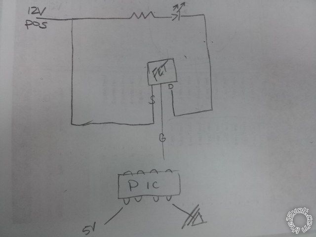
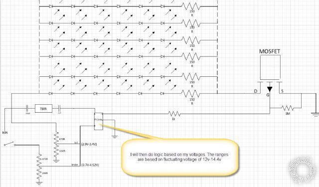
As to the FET, as I see it, any N-type (aka N-ch or N-S) MOSFET (ie, power FET) with copious Amperage handling.
Whilst you might only need a few Amps, I'm thinking of the many 60A to 120A MOSFETs I have bought for $2-$3 from markets or normal electronics chains. They are often the common TO-220 package (same as the bigger 1A or 1.5A 7805 etc voltage regulators).
Why not (a 60A MOSFET etc)?
All we care about is sufficient volts to turn it on (eg, Gate to be 4-5V higher than Source) since they are all low current (uA compared the the mA the PIC can supply).
They have no "gain" per se - not like a transistor where you require (say) mA for its Base (Gate) and might then only get out 100mA or 1A so then you need another transistor to increase to multi-Amps. (Or make or get a "Darlington Pair" which is 2 transistors with a smaller driving a larger to give gains over 1,000 or 10,000 to get from mA to (say) 10A output.)
And so what if your FET can handle 120A and you only need 20mA or 2A or 20A?
Simply put, up to a 5 volt Vgs "fully on" rating, and more than (say) 2A or 10A output (Ids). (Vgs - the max V from G to S - is usually over 50V which is more than enough for our 12V (or 14.4V etc) circuit.
See what's around that is N-channel; has no more than 4-5V Vgs for fully on (so the PC can control it); handles enough Amps (10A or more?); has suitable packaging (eg, 3 pins, TO-220 etc); and is CHEAP.
A final check might be its Rds = Resistance between Drain & Source when (fully) on, but even if as high as 1 or 2 Ohms, it's insignificant compared to the 120R or 150R LED resistors. (120R in 10 parallel strings means effectively 120/10 = 12R which is stil reasonably higher than 1-2R. And MOSFETs usually have resistances of mill-R (milli-Ohms) - especially high-current MOSFETS.)
The only warning with FETs and MOSFETs - they can be damaged by static discharge, but most modern devices have static protection (ie, inbuilt spike-protection diodes).
Otherwise (or anyhow) handle with care. Try not to touch the pins unless you are "grounded".
[ Static electricity can be hundreds or thousands of Volts but at VERY low current, hence most components simply "short out" any static. But since FETs only require nA (ie, they have VERY high impedance/resistance between terminals), the static voltage may not be shorted out and may instead puncture the device - eg, 100V static breaking thru the 60V Vds rated D-S or breaking thru the Gate to D or S).
]
Mind you, back when CMOS was popular, the same warnings applied (and still do). However I never bothered about earth/ground wrist-straps tied to conductive surfaces. I'd leave them in tinfoil (pins thru tinfoil) or their conductive foam etc and handle the tinfoil or foam, and touch the destination circuit with my other hand before fitting the CMOS chip (or FET) to the circuit.
IE - use your body/hands to equalise/connect all voltages in case static was present.
I never had any problem - at least none that I know of.
Actually I'm not sure if the PIC has similar warnings, though I don't recall any. (It probably has static protection. Certain uPC chips may not. Are we allowed to "touch" the pins on Intel i5 chips etc?)
For LEDs that require dimming, I have concluded that PICs are the answer.
Unlike the old days when - for example - vehicle dome-lamps could be dimmed with a simple "analog" decay circuit, LEDs must be PWM'd (ie, voltage held constant but with a decaying -cum- chopped current).
(As for new days & LEDs, I'm not even bothering with HIDs. IMO LEDs are not that far off. Well, they are here now, but I mean in my
affordable way.)
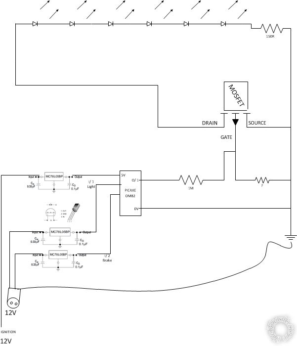
Even for a simple LED dimmer where a 555 with a handful of components can be used, a PIC only requires the 2 programming resistors and a similar pot (variable resistor) to set the brightness, but no timing caps or resistors or diodes.
Sure, the PIC might need an output buffer (ie, "amplifier" for current gain - eg, a FET or transistor) but so to does the 555 if more than ~200mA.
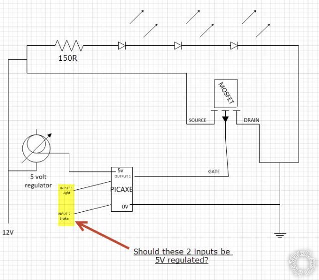
And the PIC needs a 5V regulator, but the 555 must have some protection from the higher spike voltages in cars etc, and it needs caps due to internal high-current switching (which can otherwise cause false triggering).
And for power conservation, the 555 uses a minimum of 10mA (plus whatever output current). What's the PIC use - 7nA in standby? Not even 1uA when in operation? (I too must check its specs!).
And with an 08 PIC being only a couple of dollars more than a 555...
Yeah - PIC is the way.
BTW - I called you "Master" because of your massive research etc.
Also that you seem to have adopted the PIC within days. I've held off for a decade - or is that 2 decades now?
[ Admittedly I stuck to uPCs for the big stuff I want(ed) to do. But now that the 08M2 has the same program space as its bigger family, it has greater application. Still though, I've know for years that a single PIC could do what multiple other chips and components cold do. Now wouldn't you think that an experienced ex-pert like me would have jumped sooner? Then again, not that I have necessarily built any of my intended projects. And noting "ex-pert" as in a "
has been - drip". ]


 ajm
ajm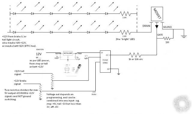
 Printable version


