the12volt.com spacer
icon

2012 odyssey, remote start, d2d vs w2w


Post ReplyPost New Topic
< Prev Topic Next Topic >
civiltoatee 
Member - Posts: 24
Member spacespace
Joined: August 17, 2012
Location: Minnesota, United States
Posted: August 28, 2012 at 11:19 AM / IP Logged  

For some reason, the FLCAN image did not appear.  Here is a link to the install guide to be downloaded:

http://www.flashlogic.com/product/product/product_id/51

Here goes.  This is for an '12 Odyssey with two power sliding side doors and a power lift gate.  From reading the FLCAN info it does not look like it will allow for the sliders to work after a R/S without some extra relays.  I am not concerned about the sliders working after R/S, but I do want them to work from the remote when the van was not R/S'd.  I would also like the power liftgate to work with the remote.

I have also downloaded from DirectWire the wiring specifics for the van and the color photos of the four main connection areas: Ignition switch 5-pin plug, Canbus 7-pin plug, headlight 12-pin plug, and brake switch 4-pin plug.  This should help with the connections to the van. 

My main concern is making just the necessary connections from the brain to the FLCAN and to the van.

Starting at the main ignition harness:

YELLOW ........... IGNITION --->  Van, Blue Ignition wire

RED ..............12V (Battery) ---> Van, White ignition wire or should I get this directly from the battery

ORANGE ...ACCESSORIES ---> Van, orange acc. wire

PURPLE ............. STARTER ---> Van, yellow starter

GREEN ............ 5th RELAY ---> No idea where this goes or what it is for

RED ............+12V (Battery) ---> White at ignition or battery, same question as above


5 Pin Secondary Harness

BLACK (–) Chassis ground ---> Van, good chasis ground

PURPLE (AC) TACH input ---> FLCAN, Tach AC output PURPLE / wh

GRAY (–) Hood Switch input ---> FLCAN, Hood status ouput yellow

ORANGE (+) Brake Switch input ---> FLCAN, Brake output grey/red

YELLOW (+) +12 V Fused Parking Light output ---> To Van? Where? Directed printout shows wire in the passenger kick fuse box

civiltoatee 
Member - Posts: 24
Member spacespace
Joined: August 17, 2012
Location: Minnesota, United States
Posted: August 28, 2012 at 12:33 PM / IP Logged  

The next harness is the 12 wire accessory harness:

Blue (-) trunk output ---> FLCAN trunk (-) input RED / white

Brown (-) lock output ---> FLCAN lock/arm (-) input GREEN/ black

Green (-) unlock output ---> FLCAN unlock (-) input blue/black

WHITE/ Brn (-) arm output ---> Is this used? Connected to ?

WHITE/ green (-) disarm output ---> Disarm (-) input brown

Blue/wh (+) pos. door input ---> To van? "used in vehicles the use a positive switching dome circuit" either this or #11 below?

WHITE/ org (-) Starter kill ---> Should I connect this?  If so, I will need a relay?

Orange (-) Parking brake ---> Not used-only for MT cars?

Purple (+) siren output ---> connect to siren. How do I know which side of the siren is (+)? Should the other leg be chasis grnd?

White (-) GWR ---> FLCAN GWR input (-) Blue/wh

Grey (-) Door input ---> To van? "used in vehicles the use a negative switching dome circuit" either this or #6 above?

Yellow (+) glow plug ---> not used

5-pin Harness

Gray/light blue (-) trunk input ---> FLCAN trunk status output (-) Yellow/red

WHITE/ purple (-) horn output ---> To van?  Do I need this with a siren?

BLACK/ green (-) Aux 2 output ---> Not used?

BLACK/ Brown (-) priority door output ---> I would like this to work, but where to connect?

Yellow (-) parking light output ---> To Van grey headlight switch BLACK/ white.  Use instead of #5 on 5-pin secondary harness, not both.

civiltoatee 
Member - Posts: 24
Member spacespace
Joined: August 17, 2012
Location: Minnesota, United States
Posted: August 28, 2012 at 1:25 PM / IP Logged  

Should the FLCAN be simply taped to the top of the brain mod or is there reason for them to be separate? A number of the wire descriptions on the FLCAN have asterisk next to them, but the * is never explained (i.e. Brake (+) output, trunk, hood, and door status (-) output, Tach AC output, E-brake status (-) output).

Now, going to the FLCAN and identifying unused wires that the diagram says should be connected (starting in upper left corner of diagram working CCW):

Ground Black ---> Van, directly to the chasis ground or can this be spliced to the brain ground?

12v (+) Red ---> Van, spliced to brain 12v or spliced into ignition 12v separate from brain or directly to battery?

Left sliding door (-) input purple / YELLOW ---> ?

Right sliding door (-) input PURPLE / black ---> ?

Starter (+) input BLACK/ white ---> ? Could this be used for the starter kill output #7 on the 12-pin harness? Wrong polarity?

E-brake status output (-) green ---> Autostart brain diagram/instructions said this was not necessary for AT, but FL says it is required and "knows" the Odyssey is AT. Is it required?

Three canbus wires canh, canl, keydata---> Van, canbus

Ignition pink ---> Van. Should join this with the brain's ignition wire or, as the FL diagram shows, splice a different, separate signal at the canbus yellow wire?

Trunk and Door Status (-) output ---> ? Could the door status be from pin #6 or #11 from the 12-pin accessory harness?

Ground (second grnd, different harness) white ---> Van, from the symbol it looks like it should definitely be chasis ground

WHITE/ black (-) output ---> Van? Says to < size=1 face=DIN-Black>< size=1 face=DIN-Black>CONNECT TO DRIVER DOOR PIN TO TURN OFF HEADLAMP ON VEHICLES EQUIPPED WITH AUTOMATIC HEADLAMP  Is that the Odyssey?

I know this is a lot of info, but there are not a lot of questions here.  Thanks for any help you can give.

kreg357 
Platinum - Posts: 7,827
Platinum spaceThis member has made a donation to the12volt.com. Click here for more info.spaceThis member has been recognized as an authority in Electrical Theory. Click here for more info.spaceThis member has been recognized as an authority in Mobile Security and Convenience. Click here for more info.spacespace
Joined: January 30, 2009
Location: Pennsylvania, United States
Posted: August 28, 2012 at 7:00 PM / IP Logged  

Main Ignition Harness AutoStart

YELLOW IGNITION --->  Van, Blue Ignition wire
RED 12V (Battery) ---> Van, White ignition wire   Rated at 50 Amps
ORANGE ACCESSORIES ---> Van, orange acc. wire
PURPLE STARTER ---> Van, yellow starter
GREEN RELAY ---> Red ACC2 at ignition switch   Set jumper for ACC2
RED +12V (Battery) ---> White at ignition  Rated @ 50 Amps

5 Pin Secondary Harness  AutoStart

BLACK (–) Chassis ground ---> Van, good chasis ground
PURPLE (AC) TACH input ---> FLCAN, Tach AC output PURPLE / white
GRAY (–) Hood Switch input ---> FLCAN, Hood status ouput yellow ( if van has factory hood pin )
ORANGE (+) Brake Switch input ---> FLCAN, Brake output grey/red
YELLOW (+) +12 V Fused Parking Light output ---> Don't need.  Use (-) Parking Light Output
          from other 5 Pin harness.

The next harness is the 12 wire accessory harness:   AutoStart

Blue (-) trunk output ---> FLCAN trunk (-) input RED / white Does van have p[oer hatch?
Brown (-) lock output ---> FLCAN lock/arm (-) input GREEN/ black
Green (-) unlock output ---> FLCAN unlock (-) input blue/black
WHITE/ Brn (-) arm output ---> Not used
WHITE/ green (-) disarm output ---> Disarm (-) input brown
Blue/wh (+) pos. door input ---> Not Used
WHITE/ org (-) Starter kill ---> Optional, need 30/40 Amp SPDT relay
Orange (-) Parking brake ---> Not used-only for MT cars?  Yes, not needed.
Purple (+) siren output ---> connect to siren. Should be Red lead.  Black lead to ground.
White (-) GWR ---> FLCAN GWR input (-) Blue/white
Grey (-) Door input ---> To FLCAN Yellow/Black
Yellow (+) glow plug ---> not used

5-pin Harness AutoStart

Gray/light blue (-) trunk input ---> FLCAN trunk status output (-) Yellow/red
WHITE/ purple (-) horn output ---> Optional
BLACK/ green (-) Aux 2 output ---> Sliding door
BLACK/ Brown (-) priority door output ---> Think FLCAN gives priority unlock.  Test.
Yellow (-) parking light output ---> To Van grey headlight switch BLACK/ white. Yes.
            Don't  use (+) Parking Light Output.

FLCAN  flashed with FLC-AL(DL)-HA3-EN

Ground Black ---> Can be spliced to the brain ground wire, they go to the same place.

12v (+) Red ---> Van, spliced to brain 12v Red
Left sliding door (-) input purple / YELLOW ---> AUX2
Right sliding door (-) input PURPLE / black ---> Trunk Output, if unlock unlocks the trunk ( no power hatch )
Starter (+) input BLACK/ white ---> to thick Purple of R/S brain
E-brake status output (-) green ---> not necessary for AT
Three canbus wires canh, canl, keydata---> Van, canbus
Ignition pink ---> as the FL diagram shows, at the transponder plug, yellow wire.
Trunk and Door Status (-) output ---> To R/S brain as shown above
Ground (second grnd, different harness) white ---> Van, or R/S brain ground wire.  They go to the same place.
WHITE/ black (-) output ---> Van, CONNECT TO DRIVER DOOR PIN if your van has AUTOMATIC HEADLAMP 

Soldering is fun!
kreg357 
Platinum - Posts: 7,827
Platinum spaceThis member has made a donation to the12volt.com. Click here for more info.spaceThis member has been recognized as an authority in Electrical Theory. Click here for more info.spaceThis member has been recognized as an authority in Mobile Security and Convenience. Click here for more info.spacespace
Joined: January 30, 2009
Location: Pennsylvania, United States
Posted: August 28, 2012 at 7:10 PM / IP Logged  

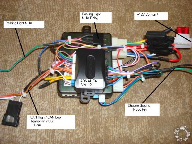
If there is room under the dash to fit the R/S brain and bypass module joined together, that is how I usually do it.  Keeps things neat and all together.  Make the bench prep easier.

2012 odyssey, remote start, d2d vs w2w - Page 2 -- posted image.

Soldering is fun!
civiltoatee 
Member - Posts: 24
Member spacespace
Joined: August 17, 2012
Location: Minnesota, United States
Posted: August 28, 2012 at 9:32 PM / IP Logged  

Wow, thanks for the quick and thorough response and the piggyback image.  It looks very tiddy. Thanks!

I have a couple of follow up questions:

GREEN RELAY ---> Red ACC2 at ignition switch Set jumper for ACC2 (what does this do or maybe I don't need to know?)

RED +12V (Battery) ---> White at ignition Rated @ 50 Amps (can both of these be twisted together and sollder spliced at the same location on the white wire? Or should they each have their own separate splices into the white wire/)

GRAY (–) Hood Switch input ---> FLCAN, Hood status ouput yellow ( if van has factory hood pin ) (There is a pair of wires going to the hood latch, hopefully that means it will work?)

YELLOW (+) +12 V Fused Parking Light output ---> Don't need. Use (-) Parking Light Output from other 5 Pin harness.(Got it. In general do you completely cut off unused wires right down to the nub at the harness plug or leave a little in case you might need it later?)

Blue (-) trunk output ---> FLCAN trunk (-) input RED / white Does van have power hatch? (Yes, it has power hatch and two power sliders.  It sounds like this unit maybe only has two available channels for aux functions like sliders and rear lift? Could I get the other slider or rear lift with a hard wired relay?)

WHITE/ org (-) Starter kill ---> Optional, need 30/40 Amp SPDT relay (This is strictly about securtiy, right? Is this different or better than the factory "security" kill?)

Purple (+) siren output ---> connect to siren. Should be Red lead. Black lead to ground. (Do you usually place the siren under the hood?  If so, do you usually ground it there or bring the ground back thru the firewall with the + and use the inside chasis ground? If under the hood, can the siren be horizontal rather than pointed down?)

Grey (-) Door input ---> To FLCAN Yellow/Black (Got it.)

WHITE/ purple (-) horn output ---> Optional (what would this add if I connected it? More noise?)

BLACK/ green (-) Aux 2 output ---> Sliding door (again, one slider and rear hatch or both sliders, but not all three?)

BLACK/ Brown (-) priority door output ---> Think FLCAN gives priority unlock. Test. (Does this mean I don't need to connect anything?  By test do you mean complete the install and see what happens when you push the unlock once and then again? Or should I test something during the install and if it is the "wrong" result then I may need to connect this to something?)

Yellow (-) parking light output ---> To Van grey headlight switch BLACK/ white. Yes. Don't use (+) Parking Light Output.(Got it.)

FLCAN flashed with FLC-AL(DL)-HA3-EN (yes, I have an OL-Loader cable on the way)

Trunk and Door Status (-) output ---> To R/S brain as shown above ( Got it. Trunk I already had, but thought I had missed)

WHITE/ black (-) output ---> Van, CONNECT TO DRIVER DOOR PIN if your van has AUTOMATIC HEADLAMP (What is automatic headlamp? Could that be the same as 'Dome Supervision' on the Directwire sheet for the Odyssey?)

I guess the big outstanding question is can I get both sliders and the power hatch to function from the remote?  There is room to mount both up and under the dash, so I will simply double sided foam the brain and FLCAN together.

Thanks again, so much for all of your help!


kreg357 
Platinum - Posts: 7,827
Platinum spaceThis member has made a donation to the12volt.com. Click here for more info.spaceThis member has been recognized as an authority in Electrical Theory. Click here for more info.spaceThis member has been recognized as an authority in Mobile Security and Convenience. Click here for more info.spacespace
Joined: January 30, 2009
Location: Pennsylvania, United States
Posted: August 28, 2012 at 10:44 PM / IP Logged  

Green Relay output is available to power the vans ACC2 wire ( no extra parts needed ).  The

ACC2 circuit might only power non-essential things like radio, power windows, etc.  Don't have
the vehicles diagrams to be sure.

Think I would strip about an inch of insulation off the White 50 A wire and solder both Red

+12V supply wires individually along that section.  Even a short 3 inch section of Red wire
carrying the whole 50 Amp load could get warm during remote start.

Hood Status - Does the van have a factory alarm?  Does it go off if you park / lock the van

while sitting inside, wait 2 minutes and pop the hood?  If yes, then the FLCAN can obtain that
hood status and pass it along to the R/S brain.

Power Trunk - Ok, Trunk Release will open the power hatch, AUX2 can do either sliding door. 

Depending on how the AutoStart unit implements the priority unlock, you could use that wire for
the other sliding door.  ( You could diode isolate and use the AUX2 output to open both doors at
once...)  Here is a little note from iDatalink that is easy to miss...
* When vehicle is remote started, feature will not be functional.
Use traditional hardwired installation method for feature to be functional during remote start.
That applies to the power hatch and both sliding doors.  2012 odyssey, remote start, d2d vs w2w - Page 2 -- posted image.

Starter Kill - Looks like it's only starter kill, not anit-grind.  While you must cut the vehicles

Starter wire, it will prevent the ignition key from starting the vehicle while the AutoStart is
locked/alarmed.  Could slow down a thief but adds a possible point of failure if the solder and
insulation isn't up to par.

Sirens - Depends how serious you are about theft prevention.  Serious is two sirens, one for

external noise and the second for internal noise.  While most better quality sirens are weather
resistant, mounting them somewhere they won't get splashed, pointed down for drainage is safest.

Horn - Yes and as a back up source.

AUX2 - See above.  This is where system planning comes in.  ( Recently did a convertible and

needed plenty of AUX outputs )

Priority Unlock - Yes, just connect the R/S brain Unlock to FLCAN Unlock.  The FLCAN might do

the drivers door with the first AutoStart Unlock button press and all the rest with the second
press ( within three seconds ).

Auto-Headlights - The headlight switch has an "Auto" position.  In this setting the lights come on

automatically when the ambient light ( as monitored by a sensor on the dash ) decreases ( dusk/
night or tunnels).  Might be optional on your van.

Double sided foam will work.  I use a hot glue gun.  Also get some 18" long tie wraps to run thru the

R/S "ears" and around something like a thick harness or support bracket for installation.

Soldering is fun!
kreg357 
Platinum - Posts: 7,827
Platinum spaceThis member has made a donation to the12volt.com. Click here for more info.spaceThis member has been recognized as an authority in Electrical Theory. Click here for more info.spaceThis member has been recognized as an authority in Mobile Security and Convenience. Click here for more info.spacespace
Joined: January 30, 2009
Location: Pennsylvania, United States
Posted: August 29, 2012 at 5:49 AM / IP Logged  

Just realized you mentioned the OL-Loader cable to flash the FLCAN with the correct firmware.

The FlashLogic FLCAN bypass is a re-badged iDatalink bypass module.  If you click on the "Flash"
button in the link you provided, you will see the WEbLink 5.0 Log-In screen.  Same restrictions
as the iDatalink module flash WEB site.    2012 odyssey, remote start, d2d vs w2w - Page 2 -- posted image.

Soldering is fun!
civiltoatee 
Member - Posts: 24
Member spacespace
Joined: August 17, 2012
Location: Minnesota, United States
Posted: August 29, 2012 at 12:03 PM / IP Logged  

Thanks again, you were up late and up early.

Hood Status - Does the van have a factory alarm? Does it go off if you park / lock the van

while sitting inside, wait 2 minutes and pop the hood? If yes, then the FLCAN can obtain that
hood status and pass it along to the R/S brain. (Car does have factory alarm, but I have not tested, yet as you described)

Power Trunk - Ok, Trunk Release will open the power hatch, AUX2 can do either sliding door.

Depending on how the AutoStart unit implements the priority unlock, you could use that wire for
the other sliding door. ( You could diode isolate and use the AUX2 output to open both doors at
once...) Here is a little note from iDatalink that is easy to miss...
* When vehicle is remote started, feature will not be functional.
Use traditional hardwired installation method for feature to be functional during remote start.
That applies to the power hatch and both sliding doors (I did realize that this was the case.  I am not concerned about not being able to using sliders or hatch during R/S, but I do want them to work otherwise.  I assume the unlocks will work during R/S?)

Starter Kill - Looks like it's only starter kill, not anit-grind. While you must cut the vehicles

Starter wire, it will prevent the ignition key from starting the vehicle while the AutoStart is
locked/alarmed. Could slow down a thief but adds a possible point of failure if the solder and
insulation isn't up to par. (I am not going to do this.)

AUX2 - See above. This is where system planning comes in. ( Recently did a convertible and

needed plenty of AUX outputs ) -- (See just below)

Priority Unlock - Yes, just connect the R/S brain Unlock to FLCAN Unlock. The FLCAN might do

the drivers door with the first AutoStart Unlock button press and all the rest with the second
press ( within three seconds ). --- (The feature sheet for the FLCAN Oyd '12 says it does priority unlock.  Therefore, I will plan to use the A/S priority unlock wire output for the right slider and Aux2 output for the left slider. I assume that somehow I will be able to assign Aux2 and priority unlock to simple combination of remote buttons (i.e. Func + something) to get each slider to open. Would I also be correct in assuming that since a second push of the factory remote closes an open slider that pushing the AUX2 or priority button will also close each slider?)

Auto-Headlights - The headlight switch has an "Auto" position. In this setting the lights come on

automatically when the ambient light ( as monitored by a sensor on the dash ) decreases ( dusk/
night or tunnels). Might be optional on your van. (This is the only thing I am still completely confused by. Does the term headlamp refer to the dome light(s) or the actual front headlights?  If it is headlights, what would that have to do with the driver door pin? Why would there be an output from the FLCAN directly to the van?  What happens if I do not hook it up? Sorry, I just don't get this one)

Otherwise, I am ready-to-go.  BTW, I do have registered access to the FL/Omega/idatalink webloader thru their website(s). I have watched a youtube video about install the Honda OEM R/S system and there is a nice bracket on the left side of the underdash area made just for their brain.  I will be using that location for mounting my brain/FLCAN.

Regarding testing each wire.  It looks like I need to connect about 12 wires to the van. For the AS: Harness1, 1-6, Harness2, Ground only, Harness3, none, Harness4 parking light output (-). For FLCAN: 4 at the transponder plug, 2-Grounds, spliced with AS brain ground, +12V spliced with the AS brain +12V and, possibly, the headlamp/doorpin connection I still don't understand.  I can and will test the Harness1 connections.  I assume I do not/cannot test the four wires at the transponder plug?  That only leaves the parking lot output (-).  I will have to admit that I am not sure exactly how to use a DMM to determine if a wire/leg is (-).

Thanks again.

kreg357 
Platinum - Posts: 7,827
Platinum spaceThis member has made a donation to the12volt.com. Click here for more info.spaceThis member has been recognized as an authority in Electrical Theory. Click here for more info.spaceThis member has been recognized as an authority in Mobile Security and Convenience. Click here for more info.spacespace
Joined: January 30, 2009
Location: Pennsylvania, United States
Posted: August 29, 2012 at 4:40 PM / IP Logged  

Hood Status - You should be good.  Just verify that raising the hood during R/S will shut down the engine.  If not, install the hood pin supplied with the

AutoStart unit.

Yes, the Lock and Unlock function should work during R/S.

Yes, a second AUX2 output ( or trunk release ) should close the sliding door ( hatch ), if it was open.

If you have AutoHeadlights and remote started your van at night, the headlights would come on if the switch was in AUTO.  If the R/S timed out ( 15 minutes )

or you turned it off with the remote, the van would keep the headlights on until it saw a door open ( or sunlight...).  Could lead to a dead battery.  The
FLCAN outputs a (-) signal on that wire and when connected to the van's door trigger wire, will fool the van into thinking the door was opened & closed,
thereby turning off the headlights.

It always pays to test and verify the wires that you can ( non-data wires ).  For the (+) ignition wires, set the DMM to 20V DC, Black lead to chassis ground

and Red lead to suspect wire.  The DMM should go to +12V when the signal is present.  For the (-) type wires ( Parking Lights ), set the DMM to 20V DC,
connect the Red lead to +12V constant ( White 50A wire @ ignition harness ) and the Black lead to the suspect wire.  The DMM will read +12V with the
signal present ( parking lights on ).  The install guides from iDatalink are always very accurate on wire color, location and function.  On the chassis
ground wires, solder on a terminal ring and make a solid mechanical connection to the van.

Never used an AutoStart unit so I won't be too much help on it's features & programming ( other than what I can glean from the install guide ).

Soldering is fun!
Page of 5

  Printable version Printable version Post ReplyPost New Topic
You cannot post new topics in this forum
You cannot reply to topics in this forum
You cannot delete your posts in this forum
You cannot edit your posts in this forum
You cannot create polls in this forum
You cannot vote in polls in this forum

  •  
Search the12volt.com
Follow the12volt.com Follow the12volt.com on Facebook
Friday, July 18, 2025 • Copyright © 1999-2025 the12volt.com, All Rights Reserved Privacy Policy & Use of Cookies
Disclaimer: *All information on this site ( the12volt.com ) is provided "as is" without any warranty of any kind, either expressed or implied, including but not limited to fitness for a particular use. Any user assumes the entire risk as to the accuracy and use of this information. Please verify all wire colors and diagrams before applying any information.

Secured by Sectigo
the12volt.com spacer
Support the12volt.com
Top
the12volt.com spacer