the12volt.com spacer
icon

2012 odyssey, remote start, d2d vs w2w


Post ReplyPost New Topic
< Prev Topic Next Topic >
civiltoatee 
Member - Posts: 24
Member spacespace
Joined: August 17, 2012
Location: Minnesota, United States
Posted: August 29, 2012 at 7:23 PM / IP Logged  

I am so close I can taste in now, thanks to you 2012 odyssey, remote start, d2d vs w2w - Page 3 -- posted image.

I just checked, and the car alarm goes off when the hood is popped. 

Thanks for the explanation of the auto headlights.  I now think I get it.  On the DEI printout for the Ody there is a wire that is part of the headlight switch 12-pin plug (which is where the parking lights (-) is located) that is labeled 'autolights turnoff pink (-)'.  Would that be the same as a driver's door pin and can I use it?  If not, will I need to run a wire under the sill plate and remove the molding by the seatbelt to get to a door pin wire?

I will verify all wires, except data.  Thanks for the tip on testing (-)'s. 

I just took apart the steering column shroud to see what I was up against.  It looks like alll of the van connections except the chasis ground (and possibly the auto headlight door trigger, depending on your response to my question above) will terminate in a splice at the steering collar.  It makes it very convenient since there is already a nice Honda bundle heading to the steering column and spidering there.  I will bundle all my wires and zip tie them to Honda's bundle and then follow the Honda sub-bundles with my wires to each of the plugs.

I was a bit concerned when I saw the wire gage on most of wire connections that were not the ignition switch (very small, indeed).  In some cases it looks like I will have to peel back some of Honda's bundling tape to get enough length to splice and solder.  Is it advisable or even recommended that I unplug each of the pin-plugs while doing the splice on each? It appears that unplugging will help in making the splices easier.

I am starting on the bench work now.  Thanks for all of your help!

kreg357 
Platinum - Posts: 7,827
Platinum spaceThis member has made a donation to the12volt.com. Click here for more info.spaceThis member has been recognized as an authority in Electrical Theory. Click here for more info.spaceThis member has been recognized as an authority in Mobile Security and Convenience. Click here for more info.spacespace
Joined: January 30, 2009
Location: Pennsylvania, United States
Posted: August 29, 2012 at 8:17 PM / IP Logged  

The drivers door pin wire is more convenient than that.  Here is the info from DEI :

Door Trigger    Light Blue (-)       @ driver dash fuse box, 44 pin plug (E), pin 22
Test the same way and same DMM setup as the (-) Parking Lights.

It is normal to have to remove some factory harness sheathing to access the wires. 

Depending on whether its mesh or tape wrap, you can roll back, split or remove some
to gain access, then re-wrap as necessary.  Following the factory runs is a good idea
and be sure to verify clearances and no chaffing with the tilt / telescopic steering
wheel function after connections are made. 

Most professional installers leave the battery connected during install.  Makes testing

and re-verification easier and prevents problems with radio codes, etc.  While I will
disconnect the main ignition harness at the ignition switch for better access, I try not
to disconnect any other plugs ( unless the battery is disconnected ).  You can throw a
code light or lose the power window function, etc.  Stay away from any harness that is
Yellow and Yellow connectors around the steering column ( air bag ).

During bench prep, you can separate and bundle the wires that go to the same general area.

Locate the brain and position it temporarily to route the wires.  Cut them to length and
solder to the vehicles wires.  Once everything is connected, install the R/S fuses, program
and test.  After that, it's just a matter of neatening up and securing everything.  Then
putting the dash trim back on and final testing.

Soldering is fun!
kreg357 
Platinum - Posts: 7,827
Platinum spaceThis member has made a donation to the12volt.com. Click here for more info.spaceThis member has been recognized as an authority in Electrical Theory. Click here for more info.spaceThis member has been recognized as an authority in Mobile Security and Convenience. Click here for more info.spacespace
Joined: January 30, 2009
Location: Pennsylvania, United States
Posted: August 29, 2012 at 10:19 PM / IP Logged  
Almost forgot.  Don't forget to set the FLCAN to "Standard Mode", 2 Blinks, and lock it
in before trying to program to the van ( top of Page 7 in the install guide ).  I usually
do that on the bench after the firmware Flash, using a +12 battery ( from an old PC UPS )
connected to the 4 Pin harness.  Makes programming to the vehicle very easy after the
R/S fuses are installed.
Soldering is fun!
civiltoatee 
Member - Posts: 24
Member spacespace
Joined: August 17, 2012
Location: Minnesota, United States
Posted: August 30, 2012 at 5:07 AM / IP Logged  

Thanks, standard mode must be for W2W.

I was a little discouraged that all of the FLCAN wires won't be long enough to reach the steering column without splicing on some length.  Of course, I don't have matching colors, so splicing means a change in color designation and it's just one more thing for a newbie to keep track of 2012 odyssey, remote start, d2d vs w2w - Page 3 -- posted image.

kreg357 
Platinum - Posts: 7,827
Platinum spaceThis member has made a donation to the12volt.com. Click here for more info.spaceThis member has been recognized as an authority in Electrical Theory. Click here for more info.spaceThis member has been recognized as an authority in Mobile Security and Convenience. Click here for more info.spacespace
Joined: January 30, 2009
Location: Pennsylvania, United States
Posted: August 30, 2012 at 5:23 AM / IP Logged  

Yes, Standard Mode is for W2W installs.

Got a chuckle on the "extending the wires" comment.   2012 odyssey, remote start, d2d vs w2w - Page 3 -- posted image.   I have accumulated and saved a whole bag of various left over wires in various colors and gauges for that very purpose.   I'm always digging thru it looking for the best match for that wire that needs some extra reach.

Soldering is fun!
civiltoatee 
Member - Posts: 24
Member spacespace
Joined: August 17, 2012
Location: Minnesota, United States
Posted: August 30, 2012 at 5:38 AM / IP Logged  

Got a chuckle on the "extending the wires" comment. 2012 odyssey, remote start, d2d vs w2w - Page 3 -- posted image. I have accumulated and saved a whole bag of various left over wires in various colors and gauges for that very purpose. I'm always digging thru it looking for the best match for that wire that needs some extra reach.

I am glad to hear that as a newbie I wasn't just missing something obvious.  Although I have already mounted the FLCAN to the roof of the AS brain, I may consider straping it with ties 6" to 12" from the brain to the Honda wire bundle going to the steering column.  Only if that gets me the length I need. It's likely that the horn and parking lights (-) wires from the brain will be too short also, so dismounting the FLCAN probably won't be worth it.

kreg357 
Platinum - Posts: 7,827
Platinum spaceThis member has made a donation to the12volt.com. Click here for more info.spaceThis member has been recognized as an authority in Electrical Theory. Click here for more info.spaceThis member has been recognized as an authority in Mobile Security and Convenience. Click here for more info.spacespace
Joined: January 30, 2009
Location: Pennsylvania, United States
Posted: August 30, 2012 at 5:55 AM / IP Logged  
Yep, you have a new car that's going to be around for many years.  You only want to do this install once, perfectly executed, so you won't have to go back in and make changes / corrections.  Nothing worse than having a weird problem like the horn beeps every time you turn left going more than 30 MPH and hit a bump in the road...  Just consider all this "under the dash" time very productive and in-expensive exercise.  2012 odyssey, remote start, d2d vs w2w - Page 3 -- posted image.  This winter, when International Falls is at -25, you'll be toasty and grinning ear to ear every morning.
Soldering is fun!
civiltoatee 
Member - Posts: 24
Member spacespace
Joined: August 17, 2012
Location: Minnesota, United States
Posted: August 30, 2012 at 11:52 PM / IP Logged  

2012 odyssey, remote start, d2d vs w2w - Page 3 -- posted image.

Here is my brain/FLCAN after bench prep.  The bundle heading down includes the 6-ignition wires, 4-immobilzer wires, horn and parking lights.  The bundle heading left includes chasis ground, siren, and door pin for the auto headlights.

Unfortunately, my cable for flashing won't arrive until next Tuesday. I may stop down at my local Best Buy and hope the installer isn't busy and see if he would be willing to flash it.  Otherwise, I can still complete the install and just pull the brain next week to flash.

Any tips on antenna or shock senser mounting?

Thanks.

kreg357 
Platinum - Posts: 7,827
Platinum spaceThis member has made a donation to the12volt.com. Click here for more info.spaceThis member has been recognized as an authority in Electrical Theory. Click here for more info.spaceThis member has been recognized as an authority in Mobile Security and Convenience. Click here for more info.spacespace
Joined: January 30, 2009
Location: Pennsylvania, United States
Posted: August 31, 2012 at 6:20 AM / IP Logged  

Nice job!  2012 odyssey, remote start, d2d vs w2w - Page 3 -- posted image.    
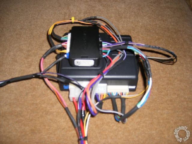
Compact and secure.  Note that you will need to see the bypasses LED briefly during vehicle programming.

Not really familiar with the AutoStart unit to help with the antenna or shock sensor.  Perhaps another forum member with AutoStart experience

can provide those answers.

Soldering is fun!
civiltoatee 
Member - Posts: 24
Member spacespace
Joined: August 17, 2012
Location: Minnesota, United States
Posted: September 02, 2012 at 4:24 PM / IP Logged  

I have most of the wires connected (of course I will still need to wait for the flashing cable).

I could not find anything in the install instruction on the shocke senser, which has a green wire that is not connected and a green loop at the brain end of the cable looping between the green and blue wires.  What should I do with the long, green, unconnected wire?

I could not figure out how to find the light blue, door pin wire in the fuse block (44-pin block, pin 22). There a lot wires here and I could not figure out how to uncover them, let alone decide which it was.  Was the wire just light blue without a tracer?

Finally,  how difficullt would it be to turn on one or both heated seats?

Page of 5

  Printable version Printable version Post ReplyPost New Topic
You cannot post new topics in this forum
You cannot reply to topics in this forum
You cannot delete your posts in this forum
You cannot edit your posts in this forum
You cannot create polls in this forum
You cannot vote in polls in this forum

  •  
Search the12volt.com
Follow the12volt.com Follow the12volt.com on Facebook
Friday, July 18, 2025 • Copyright © 1999-2025 the12volt.com, All Rights Reserved Privacy Policy & Use of Cookies
Disclaimer: *All information on this site ( the12volt.com ) is provided "as is" without any warranty of any kind, either expressed or implied, including but not limited to fitness for a particular use. Any user assumes the entire risk as to the accuracy and use of this information. Please verify all wire colors and diagrams before applying any information.

Secured by Sectigo
the12volt.com spacer
Support the12volt.com
Top
the12volt.com spacer