the12volt.com spacer
icon

2007 hummer h2 viper 5704


Post ReplyPost New Topic
< Prev Topic Next Topic >
07h2 
Member - Posts: 32
Member spacespace
Joined: November 18, 2012
Posted: November 18, 2012 at 11:38 PM / IP Logged  

Hi everyone,

I'm a rookie  when it comes to 12 volt, but atleast I'm trying. Anyways I have a Viper 5704 w/ 5904( 2way) remote and Idatalink ADS AL CA. Vehicle is a 2007 Hummer H2.

I'm looking for any help pics, comments, tips, suggestions to verify I have done the intall correctly.

So far what I have accomplished, the alarm and basic wiing is hooked up. I am able to get a solid led from the control antanne, but thats all. When I try and get it in to program mode the siren will not chirp nor will the control antanne led flash.

When I hold down the arm button on the remote (1 way ) the siren chirps however the doors do not lock. Also when I hold down the disarm button on the one way remote the siren does not chirp and the doors also do not unlock.

Once again any help would be greatly appreciated.

Thanks

shortcircuit161 
Silver - Posts: 556
Silver spaceThis member has made a donation to the12volt.com. Click here for more info.spacespace
Joined: August 29, 2010
Location: United States
Posted: November 19, 2012 at 8:11 AM / IP Logged  
Did you flash the correct firmware on the ADS-AL for your vehicle? Did you follow the programming steps once installed in the Hummer?
There is also a lot of info on this vehicle in the forum if you search it.
The viper manual will tell you why you have a solid LED on the antenna.
07h2 
Member - Posts: 32
Member spacespace
Joined: November 18, 2012
Posted: November 19, 2012 at 8:55 AM / IP Logged  
Thanks for the quick reply,
No i didnt flash the ads al. Ill try and get that done and post a update as soon as possible.
07h2 
Member - Posts: 32
Member spacespace
Joined: November 18, 2012
Posted: November 19, 2012 at 5:17 PM / IP Logged  
07h2 wrote:
Thanks for the quick reply,
No i didnt flash the ads al. Ill try and get that done and post a update as soon as possible.
Just ordered the weblink will bew a few weeks before it shows up. Ill update as I go along.
07h2 
Member - Posts: 32
Member spacespace
Joined: November 18, 2012
Posted: November 21, 2012 at 2:08 AM / IP Logged  
Its gonna be a couple of weeks before I can get the module flashed so I decided to do some homework.
I found this on another thread and was wondering if it applied
Try this:
Viper H3/        Yukon
1.Pink (+)Ignition 1 Input/Output        - Pink wire, shows +12V in run and start positions
2.RED / White (87) Flex (30A Fused)   - Red @ Ignition Switch Harness
3.Orange (+)Accessory Output  - Orange wire, shows +12V in run but not start position
4.Violet (+)Starter Output (Car Side Of Starter Kill) - Starter side of purple wire (cut), shows +12V in start position
5.Green (+)Starter Input (Key Side Of Starter Kill) - Ignition switch side of above purple wire
6.Red Ignition 1 Input (30A Fused)   - Red @ Ignition Switch Harness
7.Pink/White (30) Flex Relay Output - White @ Ignition Switch Harness ***Viper Menu 3, Item 8, Opt 1
8.Pink/Black (87a) Flex Relay Input   - NC
9.RED / Black Acc/Starter (30A Fused) - Red @ Ignition Switch Harness
10.No Connection
Brown ACC2 wire at ignition switch harness requires extra 30/40A SPDT relay :
Pin 85 to Viper Orange (-)200mA Accessory2 Output
Pin 86 and 87 to +12V Constant thru 20A fuse
Pin 30 to Brown ACC2 @ Ignition Switch Harness
Pin 87A not used - insulate
07h2 
Member - Posts: 32
Member spacespace
Joined: November 18, 2012
Posted: November 21, 2012 at 2:22 AM / IP Logged  
on the h2 aux/shutdown/trigger harness which connections can I omit?
h2/1     (-)200ma ignition/flex relay control output
h2/2     (-) Neutral Safety input
h2/3     (-) 200ma 2nd status/rear defogger output
h2/4     (-) 200ma oem alarm disarm output
h2/5     (-) 200ma trunk release output
h2/6     (-) door trigger input (n/c or n/o)
h2/7     (-) 200ma dome light supervision output
h2/8     (-) 200ma horn honk output
h2/9     (-) 200ma status output
h2/10    (-) 200ma ignition 1 output
h2/11    (-) 200ma aux 3 output
h2/12    (-) door trigger input
h2/13    (-) 200ma aux 1 output
h2/14    (-) 200ma aux 2 output
h2/15    (-) 200ma aux 4 output
h2/16    (+) brake shutdown input
h2/17    (-) hood pin input (n/c or n/o)
h2/18    (-) 200ma starter output
h2/19    (-) trunk pin/ instant trigger input (n/c or n/o)
h2/20    (-) diesel wait to start input
h2/21    (-) remote start/turbo timer activation input
h2/22    (-) 200ma accessory input
h2/23    tachometer input
h2/24    (-) 200ma oem alarm arm out put
07h2 
Member - Posts: 32
Member spacespace
Joined: November 18, 2012
Posted: November 21, 2012 at 2:26 AM / IP Logged  
on the main harness of the viper does
h1/6    (-)500ma ground when armed output
get connected to anything?
07h2 
Member - Posts: 32
Member spacespace
Joined: November 18, 2012
Posted: November 21, 2012 at 2:28 AM / IP Logged  
the more i read the more i question my install, going to remove and redo everything for a more cleaner install and plan on taking pics to upload.
07h2 
Member - Posts: 32
Member spacespace
Joined: November 18, 2012
Posted: November 21, 2012 at 2:38 AM / IP Logged  
2007 hummer h2 viper 5704 -- posted image.
kreg357 
Platinum - Posts: 7,783
Platinum spaceThis member has made a donation to the12volt.com. Click here for more info.spaceThis member has been recognized as an authority in Electrical Theory. Click here for more info.spaceThis member has been recognized as an authority in Mobile Security and Convenience. Click here for more info.spacespace
Joined: January 30, 2009
Location: Pennsylvania, United States
Posted: November 21, 2012 at 6:19 AM / IP Logged  

A few thoughts / updates...

Besides the ADS USB cable, you must register on the Flash section of the iDatalink WEB site and

pass their requirements to be able to use the ADS USB cable and re-program any bypass module.
Additionally you can flash the ADS or the DBI flavor of firmware on to the module.  With the
ADS version, you must connect the bypass to the Viper in W2W mode.  With the DBI version you
could go D2D.  ( I don't use too many Viper systems so I can comment on how well DBI D2D works.)
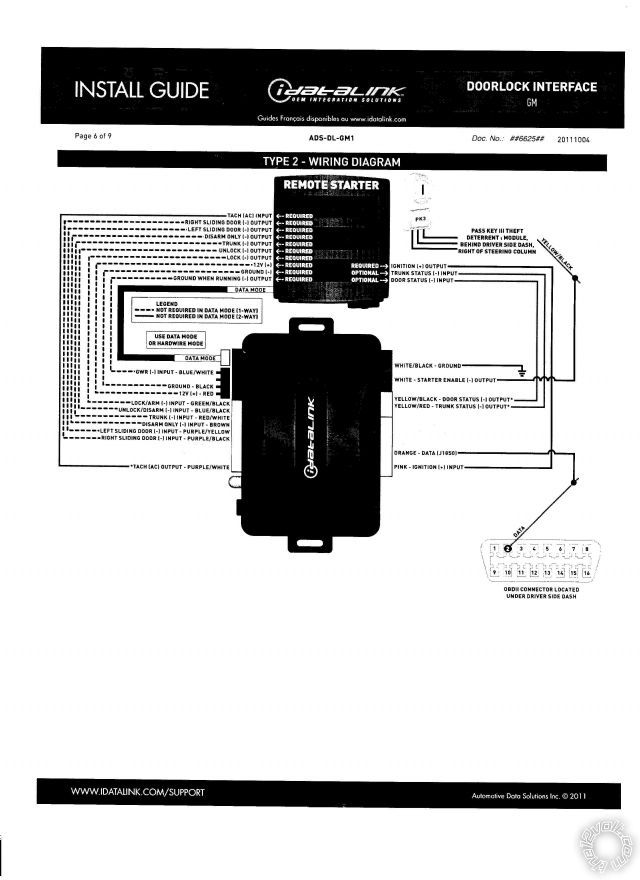
The correct firmware for your ADS AL CA is ADS AL(DL) GM1 using install guide #6611 and the
Type 3 install diagram.  If you decide to use DBI firmware and go D2D, the correct firmware
is DBI AL(DL) GM1. Here is a link to the iDatalink WEB site :  http://www.idatalink.com/support

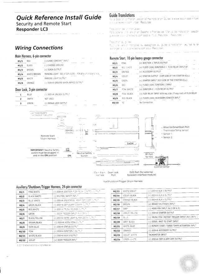
This H3 wiring will work on your 2007 H2 with this correction to the Starter wire color.

1.Pink (+)Ignition 1 Input/Output               - Pink wire  @ Ignition Switch Harness

2.RED / White (87) Flex (30A Fused)          - Red @ Ignition Switch Harness
3.Orange (+)Accessory Output    - Orange wire @ Ignition Switch Harness
4.Violet (+)Starter Output (Car Side)        - Starter side of (cut) Yellow wire @ Ignition Switch Harness 
5.Green (+)Starter Input (Key Side)          - Ignition switch side of above (cut) Yellow wire @ Ignition Switch Harness
6.Red Ignition 1 Input (30A Fused)           - Red @ Ignition Switch Harness
7.Pink/White (30) Flex Relay Output         - White @ Ignition Switch Harness ***Viper Menu 3, Item 8, Opt 1
8.Pink/Black (87a) Flex Relay Input          - NC
9.RED / Black Acc/Starter (30A Fused)       - Red @ Ignition Switch Harness
10.No Connection

Brown ACC2 wire at ignition switch harness requires extra 30/40A SPDT relay :

Pin 85 to Viper H2/22 Orange (-)200mA Accessory2 Output
Pin 86 and 87 to +12V Constant thru 20A fuse
Pin 30 to Brown ACC2 @ Ignition Switch Harness
Pin 87A not used - insulate

As for unused and necessary H2 connections :

h2/1     (-)200ma ignition/flex relay control output    N.U.

h2/2     (-) Neutral Safety input             Chassis Ground
h2/3     (-) 200ma 2nd status/rear defogger output   N.U.
h2/4     (-) 200ma oem alarm disarm output N.U.
h2/5     (-) 200ma trunk release output           N.U.
h2/6     (-) door trigger input (n/c or n/o)          To ADS Door Status output ( only covers front doors )
h2/7     (-) 200ma dome light supervision output      N.U.
h2/8     (-) 200ma horn honk output      Optional
h2/9     (-) 200ma status output          To ADS GRW in W2W mode
h2/10    (-) 200ma ignition 1 output    N.U.
h2/11    (-) 200ma aux 3 output           N.U.
h2/12    (-) door trigger input                To ADS Door Status Output in W2W mode
h2/13    (-) 200ma aux 1 output   N.U.
h2/14    (-) 200ma aux 2 output           N.U.
h2/15    (-) 200ma aux 4 output           N.U.
h2/16    (+) brake shutdown input                   To ADS Brake output in W2W mode
h2/17    (-) hood pin input (n/c or n/o)             To supplied hood pin switch ( N.C. )
h2/18    (-) 200ma starter output         N.U.
h2/19    (-) trunk pin/ instant trigger input (n/c or n/o)  To ADS Trunk Status output in W2W mode
h2/20    (-) diesel wait to start input                 N.U.
h2/21    (-) remote start/turbo timer activation input              N.U.
h2/22    (-) 200ma accessory input                 To extra relay
h2/23    tachometer input        To ADS Tach output  ***Set Viper to Tach Mode, Menu 3, Item 2, Opt 4
h2/24    (-) 200ma oem alarm arm out put        N.U.

Here is Viper's info on H1/6 GWA :

This wire supplies a (-)500 mA ground as long as the system is armed. This output
ceases as soon as the system is disarmed. The GWA can be hooked up to a
window control module, a voice module or any accessory that requires a ground
when armed.

It can also be used with programming option 3-13 to provide the Anti-Grind feature.  Viper info below :

3-13 ANTI-GRIND ON: With the anti-grind On (default) the ground-when-armed
output will be active during remote start operation. This activates the starter
kill relay and prevents the customer from re-cranking the car with the key, when
doing key takeover. If accessories such as a voice module or window module are
added to the unit, it may be necessary to use the two-chirp setting to program
this feature OFF.

Re - re-doing install :

This is a fairly easy install with the ADS bypass module.  It does most everything for you.  I would mate the Viper to the
properly flashed ADS AL CA bypass module in W2W mode on the bench, prior to vehicle install.  Solder all connections
and use heat shrink tube where ever possible.  The only gotcha is the rear door pins.  To do it correctly you will
need some diodes ( 1N400x ).  Here is the info from Ready Remote :

The driver door trigger is gray/black (-) at the driver door module in the door. The RF door trigger is BLACK/ white (-)

at the passenger door module in the door. The LR door trigger is lt. blue/black (-), pin A3, and the RR is lt. GREEN/ black (-),
pin A2, they are in the purple plug at the BCM. Use all four wires and diode isolate each.

The BCM (Body Control Module) is located behind the headlight switch. It has 6 plugs in it, the purple plug is on the back.

The ADS bypass module supplies the front door triggers as previously mentioned.  You will need to diode isolate the two

rear door status wires from the truck and join them into the Vipers H2/6 Green (-) Door Trigger input which already has
the ADS (-) Door Status Output.

As always, use your DMM to locate and verify all vehicle wires ( except OBD2 Data ).

Soldering is fun!
Page of 5

  Printable version Printable version Post ReplyPost New Topic
You cannot post new topics in this forum
You cannot reply to topics in this forum
You cannot delete your posts in this forum
You cannot edit your posts in this forum
You cannot create polls in this forum
You cannot vote in polls in this forum

  •  
Search the12volt.com
Follow the12volt.com Follow the12volt.com on Facebook
Thursday, April 25, 2024 • Copyright © 1999-2024 the12volt.com, All Rights Reserved Privacy Policy & Use of Cookies
Disclaimer: *All information on this site ( the12volt.com ) is provided "as is" without any warranty of any kind, either expressed or implied, including but not limited to fitness for a particular use. Any user assumes the entire risk as to the accuracy and use of this information. Please verify all wire colors and diagrams before applying any information.

Secured by Sectigo
the12volt.com spacer
Support the12volt.com
Top
the12volt.com spacer