the12volt.com spacer
icon

f350 diesel remote starter


Post ReplyPost New Topic
< Prev Topic Next Topic >
super03duty 
Member - Posts: 24
Member spacespace
Joined: December 28, 2012
Location: Michigan, United States
Posted: January 01, 2013 at 12:54 PM / IP Logged  

Ok, so the install was a success to a degree.  the remote start works as expected.  I have not hooked up the lock/unlock wires since i dont have the DEI451m parts yet. 

Heres my issue.  I hit the lock/arm button on the remote and it tells me the drivers door is open. You open the door and lock/arm the system and it shows closed.  I know the wires are connected corectly.  (You and I have gone rounds aobut that!!LOL)  In the list I made the neg door pin trigger is not used.  Is this supposed to be that way?  I just never found a neg trigger on any of the list i looked at.  Am i hooked the the wrong truck wire or should the neg door trigger wire be hooked to the blk/blue in the truck?

The other Issue is that if i hit the unlock button on the door the alarm goes off and i have to unhook the batteries to get it to stop. The remote is unresponsive.  It does not go off if you hit the lock button on the door just the unlock.  Now remember i have not hooked up the wires from the H7 plug since i dont have the parts.  Should i just wait and see what happens when i do get them hooked up or did i do something wrong?

kreg357 
Platinum - Posts: 7,790
Platinum spaceThis member has made a donation to the12volt.com. Click here for more info.spaceThis member has been recognized as an authority in Electrical Theory. Click here for more info.spaceThis member has been recognized as an authority in Mobile Security and Convenience. Click here for more info.spacespace
Joined: January 30, 2009
Location: Pennsylvania, United States
Posted: January 01, 2013 at 1:55 PM / IP Logged  

Just noticed this.  Disconnect the H10/4 White wire if it is going to the same place as the H10/16 Violet wire.  You will need a relay to

change the H10/4 polarity to the (+) the truck needs.

H10. 20 PIN CONNECTOR  

Black / White Wire: (-) Neutral Safety Switc h Input        H1       GROUND
Black / Violet Wire: (-) 200 mA Channel 6 Programmable Output       H2       NOT USED
Pink Wire: 2-Step Unlock /Factory Disarm /Sensor By-pass    H3       PINK/LTGREEN           KICK PANEL
White Wire: (-) 200mA Dome Light Control Output        H4      BLK/LT BLUE        ***************        PASS KICK PANEL
Black / Red Wire: (-) 200 mA Channel 5 Programmable Output          H5      NOT USED
Bl ack / Green Wire: ( -) 20 0mA Chann el 4 Programmable Output   H6        NOT USED
Gray Wire: (-) 200mA Channel 2 (Trunk) Output   H7       NOT USED
Brown / White Wire: (-) 200mA Horn Output (P rogrammable) H8        BLUE STEERING COLUMN
Yellow Wire: (-) 200mA Ig nition 3 Control Output           H9       NOT USED
Blue / Black Wire: (-) 200mA Accessory 2 Control Output          H10     To extra Relay Pin 85   *** See wiring below
Blue Wire:(-) Zone 2 Negative Hood/Trunk trigger         H20        Not Used        
White / Green Wire: (-) Diesel Wait-To-Start Input          H19     VLT/OR-WT/LTGN
White / Blue Wire: (-) Instant Start and Turn Off Input     H18      Not Used
Green Wire : Zone 3 (-) Negative Door Pin Trigger         H17     NOT USED
Violet Wire: Zone 3 (+) Positive Door Trigger   H16     BLK/BLUE (+)          **************           KICK PANEL
White / Red Wire: Tachometer Signal Input        H15      WHT/PINK (-)         BCM
White / Black Wire: (-) Negative Hood Pin Safety Shut Down    H14       HOOD SWITCH
White / Violet Wire: (+) Brake Switch Shut Down Input   H13      LT GREEN (+) BRAKE SWITCH
Orange Wire: (-) 500mA Grounded Output When Armed H12       NOT USED

Soldering is fun!
super03duty 
Member - Posts: 24
Member spacespace
Joined: December 28, 2012
Location: Michigan, United States
Posted: January 01, 2013 at 4:43 PM / IP Logged  

can i set it up the same way that you told me to set up the ACC2?  I have an extra relay. 

As far as the door locks and the alarm going off????

kreg357 
Platinum - Posts: 7,790
Platinum spaceThis member has made a donation to the12volt.com. Click here for more info.spaceThis member has been recognized as an authority in Electrical Theory. Click here for more info.spaceThis member has been recognized as an authority in Mobile Security and Convenience. Click here for more info.spacespace
Joined: January 30, 2009
Location: Pennsylvania, United States
Posted: January 01, 2013 at 5:04 PM / IP Logged  

As far as the relay for Dome Light Supervision, yes same wiring.

Relay Pin 86 and 87 to +12V constant fused @ 5 Amps
Relay Pin 85 to H10/4 White
Relay Pin 30 to Truck BLACK/ Light Blue (+)

Does the truck have the domelight fade out when the door is closed?  That delay can cause problems when arming

the alarm.  Maybe programming Alarm Feature A - 3 would help.  ( Not too familiar with your R/S system.)

Soldering is fun!
super03duty 
Member - Posts: 24
Member spacespace
Joined: December 28, 2012
Location: Michigan, United States
Posted: January 01, 2013 at 6:27 PM / IP Logged  

No it does not have the fade dome lights.  can i jump power to the relay from the other installed relay or should i run its own separate power wires?

kreg357 
Platinum - Posts: 7,790
Platinum spaceThis member has made a donation to the12volt.com. Click here for more info.spaceThis member has been recognized as an authority in Electrical Theory. Click here for more info.spaceThis member has been recognized as an authority in Mobile Security and Convenience. Click here for more info.spacespace
Joined: January 30, 2009
Location: Pennsylvania, United States
Posted: January 01, 2013 at 6:44 PM / IP Logged  

You can jump it.  It draws very little current.

If the R/S is armed and you get the Dome Light to come on, it thinks a door has been opened and sets off the alarm.  The R/S is using the Dome Light as a trigger wire for the alarm, if this wire goes to +12 volts, it sets off the alarm.

Soldering is fun!
super03duty 
Member - Posts: 24
Member spacespace
Joined: December 28, 2012
Location: Michigan, United States
Posted: January 03, 2013 at 4:43 PM / IP Logged  
So I received the DEI 451M.  Did i need 2 or just 1, cause i ordered 2.  The directions are pretty clear but can you tell me what system I have?  Is it the 3 wire 12v or is it the 3 wire grounded system?
kreg357 
Platinum - Posts: 7,790
Platinum spaceThis member has made a donation to the12volt.com. Click here for more info.spaceThis member has been recognized as an authority in Electrical Theory. Click here for more info.spaceThis member has been recognized as an authority in Mobile Security and Convenience. Click here for more info.spacespace
Joined: January 30, 2009
Location: Pennsylvania, United States
Posted: January 03, 2013 at 6:13 PM / IP Logged  
Only need one 451M.  Follow the Wiring Diagram C.
Soldering is fun!
super03duty 
Member - Posts: 24
Member spacespace
Joined: December 28, 2012
Location: Michigan, United States
Posted: January 04, 2013 at 11:27 AM / IP Logged  
Thanks for all your help!!! I dont think I would have been able to do this with out your help!!  I feel like I am being a huge pain in your A@@ but i was looking at the wiring that you sent to me and was curious about the 1N4001 W/band towards RS900.  The package contains a pack of diodes and I have never delt with diodes before.  Can you please break this down for me?  Am i supposed to use a 4000 diode and a 1 diode?  And how do i hook them up?  I feel so dense!!  I want to learn this in such a bad way not only for myself but I have a coworker that is doing 2 remote starts and he looks to me for advice. 
kreg357 
Platinum - Posts: 7,790
Platinum spaceThis member has made a donation to the12volt.com. Click here for more info.spaceThis member has been recognized as an authority in Electrical Theory. Click here for more info.spaceThis member has been recognized as an authority in Mobile Security and Convenience. Click here for more info.spacespace
Joined: January 30, 2009
Location: Pennsylvania, United States
Posted: January 04, 2013 at 1:02 PM / IP Logged  

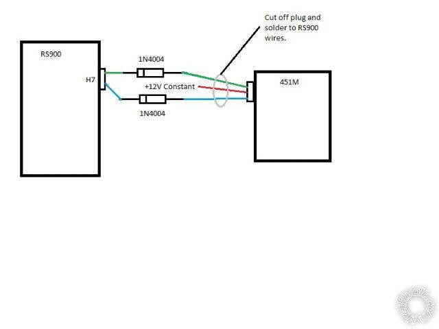
My suggestion for the diodes was due tho the RS900's door lock outputs.  They are what I call "push-pull".

When the RS900 outputs a Lock pulse, it is actually a (-) pulse followed by a (+) pulse.  Most R/S units only
output a simple (-) pulse.  The diode will block the (+) pulse and prevent it from causing damage or confusion
to the unit receiving this signal.  The 451M module kit includes only resistors.  The resistors are used
for "one-wire" door lock systems.  You won't need them.  The correct diode would be a 1N4001, 1N4004 or 1N4007.
These are the most commonly available.  They are all one amp diodes with different Peak / RMS reverse voltage
ratings.  Here is a link to a Data Sheet on these diodes :  http://www.diodes.com/datasheets/ds28002.pdf

Here is a diagram of the R/S to 451M connections :

f350 diesel remote starter - Page 3 -- posted image.

Soldering is fun!
Page of 4

  Printable version Printable version Post ReplyPost New Topic
You cannot post new topics in this forum
You cannot reply to topics in this forum
You cannot delete your posts in this forum
You cannot edit your posts in this forum
You cannot create polls in this forum
You cannot vote in polls in this forum

  •  
Search the12volt.com
Follow the12volt.com Follow the12volt.com on Facebook
Monday, June 3, 2024 • Copyright © 1999-2024 the12volt.com, All Rights Reserved Privacy Policy & Use of Cookies
Disclaimer: *All information on this site ( the12volt.com ) is provided "as is" without any warranty of any kind, either expressed or implied, including but not limited to fitness for a particular use. Any user assumes the entire risk as to the accuracy and use of this information. Please verify all wire colors and diagrams before applying any information.

Secured by Sectigo
the12volt.com spacer
Support the12volt.com
Top
the12volt.com spacer