the12volt.com spacer
icon

program pkall bypass problem


Post ReplyPost New Topic
< Prev Topic Next Topic >
blazing_nitro 
Member - Posts: 27
Member spacespace
Joined: September 23, 2012
Location: Ontario, Canada
Posted: January 07, 2013 at 4:34 PM / IP Logged  

I tried again tonight.

Without power to the module the car starts fine. Using the program sequence the car starts and then runs for 3 seconds and shuts off.

I tried reversing the IMI wires. Without power car starts fine. Using the programming the car does the same thing starts and then shuts off after 3 seconds. I repeat like 4 times nothing.

One thing I noticed is that when I disconnect the IMI wire without connecting to the module the car barely starts and doesn't even run. Where when I try to program it runs for at least 3 seconds.

The other thing I tried was plugging in the power harness in the other black port and power comes on. Repeated the above and same thing occurs. I noticed on the instructions is says to cut the black power connector and I cut the whit but they are both the same so no solution.

kreg357 
Platinum - Posts: 7,827
Platinum spaceThis member has made a donation to the12volt.com. Click here for more info.spaceThis member has been recognized as an authority in Electrical Theory. Click here for more info.spaceThis member has been recognized as an authority in Mobile Security and Convenience. Click here for more info.spacespace
Joined: January 30, 2009
Location: Pennsylvania, United States
Posted: January 07, 2013 at 5:19 PM / IP Logged  

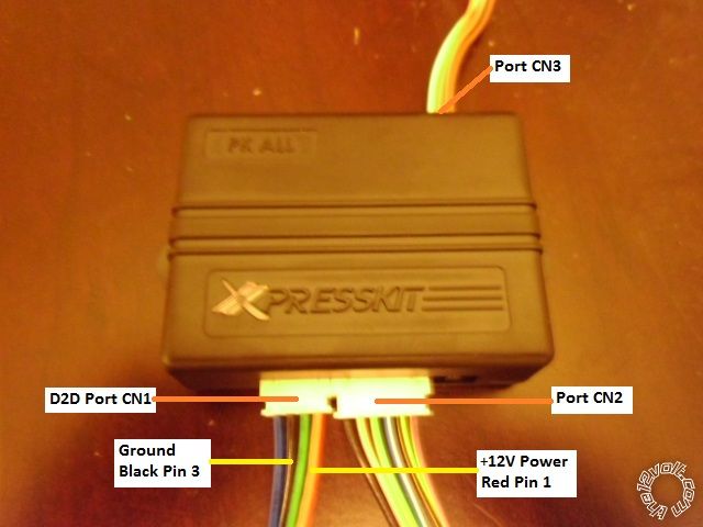
Once you cut the Purple IMI wire, the PKALL relay harness, CN3, must be plugged in or the van

won't start.

Not sure if it matters but the install guide calls for the harnesses to plugged in to the PKALL

( with button pressed ) in this order, CN2, CN3, CN1.

Below is a picture of a PKALL with the harhesses marked and the CN1 W2W install wires marked :

program pkall bypass problem - Page 2 -- posted image.

Maybe, when the CN1 Blue wire was connected to ground, it zapped the PKALL?

Soldering is fun!
blazing_nitro 
Member - Posts: 27
Member spacespace
Joined: September 23, 2012
Location: Ontario, Canada
Posted: January 07, 2013 at 10:26 PM / IP Logged  
Hi yes I think i did the correct sequence on your picture holding and releasing once light comes on but didn't work. I tried various speeds fast and slow but nothing.
I connected the blue wire to positive 12 volts as per instructions but no light came on. I read the old manual and it mentioned the red wire on pin 1. Strange instructions mention power wire could be blue or red. Terrible.
blazing_nitro 
Member - Posts: 27
Member spacespace
Joined: September 23, 2012
Location: Ontario, Canada
Posted: January 07, 2013 at 10:34 PM / IP Logged  
Forgot to mention that my pkall is version 2 software 4.06 on the back.
I'm thinking I should check the green imi wire under the dash again. When trying to connect to this wire I accidentally cut it. Twist bradded three wires together maybe something wrong with this but because I have to remove all the plastic trim again may have to try again for the weekend.
kreg357 
Platinum - Posts: 7,827
Platinum spaceThis member has made a donation to the12volt.com. Click here for more info.spaceThis member has been recognized as an authority in Electrical Theory. Click here for more info.spaceThis member has been recognized as an authority in Mobile Security and Convenience. Click here for more info.spacespace
Joined: January 30, 2009
Location: Pennsylvania, United States
Posted: January 08, 2013 at 5:58 AM / IP Logged  

Those are the current PKALL hardware and firmware versions.  No problems there.

Yes, double, even triple check all those connections at the IMI / IMO wires.  They should all be soldered and well insulated.

The CN1 Blue Data wire getting hit with +12V could still be an issue... 

Soldering is fun!
blazing_nitro 
Member - Posts: 27
Member spacespace
Joined: September 23, 2012
Location: Ontario, Canada
Posted: January 08, 2013 at 9:43 AM / IP Logged  

Got off the phone with tech support with my information.

I mentioned that the instructions I had indicated power to be connected specifically to the blue wire with the fine print saying it can vary on model. The current instructions I downloaded that must have been updated recently indicate the power to be connected to the red or blue. Obviously the red or pin 4 is correct.

The tech supported indicated that the module is protected if a user connects power to the blue wire.

He suggeseted I confirm continuity across the purle IMI wire during the programing stage. This could be an indication that the relay within the unit is stuck. What also might help to understand is that the yellow/black wire to the unit is the wire that detects the key code. The starting of the car and shut down seems to indicate that the yellow wire is not seing the code I will check for continuity along this wire to the connector as well.

blazing_nitro 
Member - Posts: 27
Member spacespace
Joined: September 23, 2012
Location: Ontario, Canada
Posted: January 09, 2013 at 11:44 PM / IP Logged  
Well I had a chance to check the wires again tonight.
I checked the continuity across the purple imi wire. When there is no power to the module there is continuity across the two ends. When the module is in the programming state there is also continuity across the wires. I don't get it.
I tried connecting just one end of the imi wire to the module in hopes of programming but both end don't work car doesn't even start.
I downloaded the fortin bypass instructions and they reference the green wire is the imi wire and the purple is the IMO wire. This is completely backward from the directed instructions. I checked instructions for the sienna by idatalink and they were same as directed.
Anybody know what would happen if I try switching the imi and IMO wires. I don't want to fry my car.
blazing_nitro 
Member - Posts: 27
Member spacespace
Joined: September 23, 2012
Location: Ontario, Canada
Posted: January 09, 2013 at 11:47 PM / IP Logged  
Forgot to mention that I checked all my connections for continuity from the pkall wire harness end to the plug under the dash and all connections are fine.
kreg357 
Platinum - Posts: 7,827
Platinum spaceThis member has made a donation to the12volt.com. Click here for more info.spaceThis member has been recognized as an authority in Electrical Theory. Click here for more info.spaceThis member has been recognized as an authority in Mobile Security and Convenience. Click here for more info.spacespace
Joined: January 30, 2009
Location: Pennsylvania, United States
Posted: January 10, 2013 at 5:29 AM / IP Logged  

Maybe I have the wrong guide, but the Fortin KeyOverRideALL install guide looks the same as the PKALL guide.  The IMI / IMO wire names, locations, colors, bypass connections and which wire gets cut seem to match up.    https://ifar.ca/download/2121/preview.html

Have you tried a new PKALL module? 

Soldering is fun!
blazing_nitro 
Member - Posts: 27
Member spacespace
Joined: September 23, 2012
Location: Ontario, Canada
Posted: January 10, 2013 at 10:23 AM / IP Logged  

Yes I too noticed that the fortin and directed instructions specifically for the Sienna were same drawing.

I know the Venza is almost same as the sienna. Downloaded the Venza manual to double check and on Page 14 it also shows the sienna information. https://ifar.ca/en/download/5801/evo-all_toyota_lexus_scion.rev-20120813.pdf

Since the revision is dated 2012 08 13 for the comprehensive manual I thought it might be better or more up to date then the sienna revision which is dated 2010 on the top of the page.

Should I switch wires?

Page of 3

  Printable version Printable version Post ReplyPost New Topic
You cannot post new topics in this forum
You cannot reply to topics in this forum
You cannot delete your posts in this forum
You cannot edit your posts in this forum
You cannot create polls in this forum
You cannot vote in polls in this forum

  •  
Search the12volt.com
Follow the12volt.com Follow the12volt.com on Facebook
Sunday, July 13, 2025 • Copyright © 1999-2025 the12volt.com, All Rights Reserved Privacy Policy & Use of Cookies
Disclaimer: *All information on this site ( the12volt.com ) is provided "as is" without any warranty of any kind, either expressed or implied, including but not limited to fitness for a particular use. Any user assumes the entire risk as to the accuracy and use of this information. Please verify all wire colors and diagrams before applying any information.

Secured by Sectigo
the12volt.com spacer
Support the12volt.com
Top
the12volt.com spacer