the12volt.com spacer
icon

2001-2003 F-150 Remote Start w/Keyless Pictorial


Post ReplyPost New Topic
< Prev Topic Next Topic >
kreg357 
Platinum - Posts: 7,795
Platinum spaceThis member has made a donation to the12volt.com. Click here for more info.spaceThis member has been recognized as an authority in Electrical Theory. Click here for more info.spaceThis member has been recognized as an authority in Mobile Security and Convenience. Click here for more info.spacespace
Joined: January 30, 2009
Location: Pennsylvania, United States
Posted: May 25, 2013 at 1:41 PM / IP Logged  

This is a DIY Pictorial guide for installing a remote start with keyless entry system into

a 2001 Ford F150 pickup truck.  The 2001 thru 2003 models should be the same.

There are a few slight variations between the trucks.  All have a PATS engine immobilizer

system.  The trucks with Factory Remote Keyless Entry have Type B (-) locks while trucks
without Factory RKE are Type C ( REV ) locks.  Tach location will vary with the engine.  This
truck had the 5.4 L Triton V-8, an automatic transmission, Factory RKE and no Factory Alarm.

For this install an Ultra Start U1272 system was used.  For the PATS bypass a Directed

1100F bypass module was the choice.   If this truck did not have Factory RKE, a Directed
451M door lock module would have been used to handle the locks.  Additional parts
included a 30/40 Amp SPDT relay ( for Accessory3 ), a tilt switch for the hood pin and the
regular solder, heat shrink tube, electric tape, tie wraps, 1N4007 diode, etc.

Disassembly :

With the engine off, insert the ignition key to ON and place the gear shift selector to the L

range.  Tilt the steering column to the lowest position and remove the upper bezel trim piece
by pulling it straight away from the instrument panel.  Return the trans selector to Park and
remove the key.  Tilt the steering wheel back to the top position.  Remove the fuse panel cover.

Remove the lower dash panel by removing the fasteners shown in the photo below :
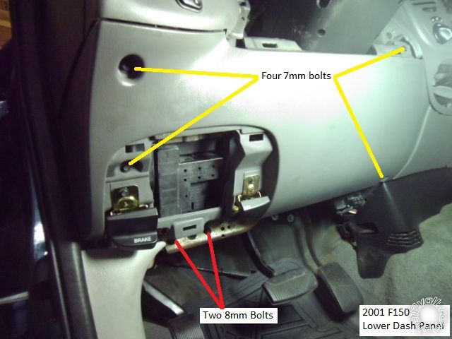
2001-2003 F-150 Remote Start w/Keyless Pictorial -- posted image.

You can also remove the parking brake release and hood release by removing the two

7mm screws that retain each to the dash panel.  There is no need to remove the steering
column trim.

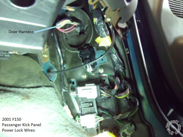
Remove the passenger door sill trim piece by lifting it straight up.  Then remove the

Passenger kick panel by pulling in straight back.  This is an easy place to locate the door
lock wires.

Wiring :

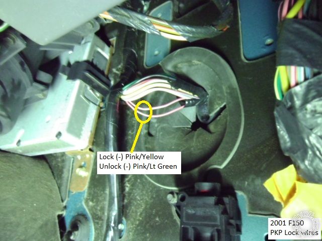
High up in the PKP is the door harness.  Factroy RKE or not, it has the Pink / YELLOW Lock

and Pink/Light Green Unlock wires.  Test to determine which system is in the truck.
2001-2003 F-150 Remote Start w/Keyless Pictorial -- posted image.

2001-2003 F-150 Remote Start w/Keyless Pictorial -- posted image.

If your truck has Factory RKE, you can also get these wires at the GEM module.  The GEM

module is mounted to the firewall behind the fuse box under the drivers dash.  If you
have the GEM module, test to see if GEM Wake-Up is necessary.  ( GEM Wake-Up is not
covered in this Pictorial, sorry. )

On the left side of the steering column is the main ignition connector shown below :
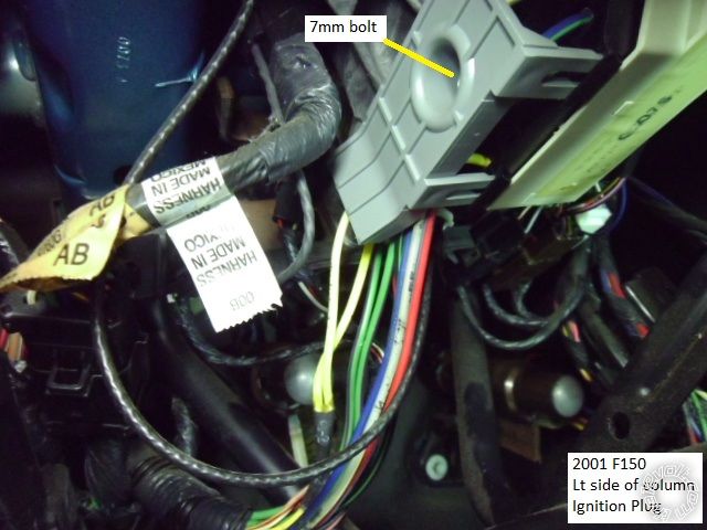
2001-2003 F-150 Remote Start w/Keyless Pictorial -- posted image.

Use a 7mm socket wrench to remove the retaining bolt.  The photo below shows the

ignition connector with the gray cover removed and all wires marked.
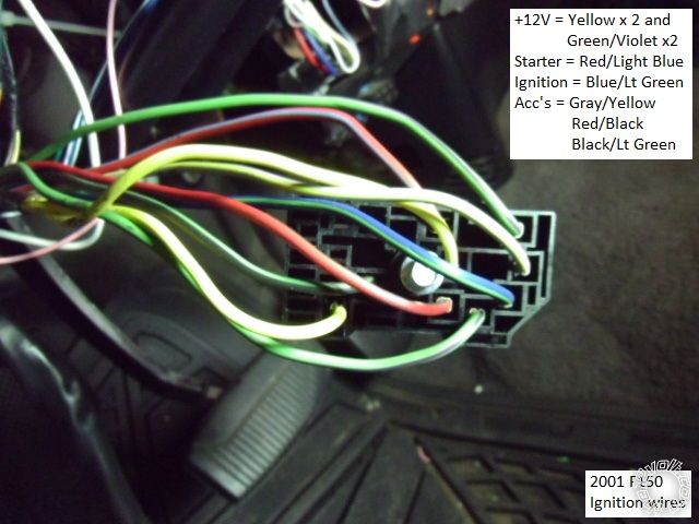
2001-2003 F-150 Remote Start w/Keyless Pictorial -- posted image.

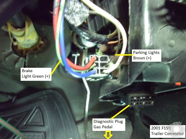
Ford makes the Parking Lights and Brake wires easy for you.  They are located in the

trailer harness connector that is to the right of the steering column by the diagnostic
connector.  Here is the connector with the wires indicated :
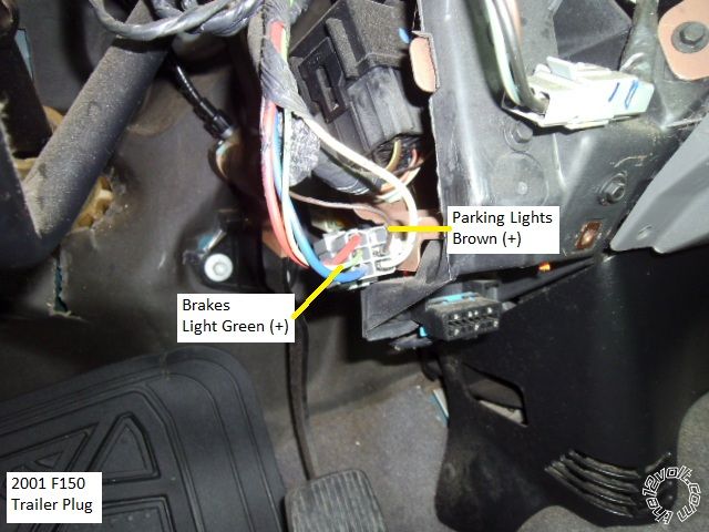
2001-2003 F-150 Remote Start w/Keyless Pictorial -- posted image.

2001-2003 F-150 Remote Start w/Keyless Pictorial -- posted image.

The Parking Lights can also be found at the Headlight Switch and the Brake wire

can be found at the top of the brake pedal, same wire colors.

The horn trigger wire is shown in the next picture.  These connectors are just to the

right of the steering column.  
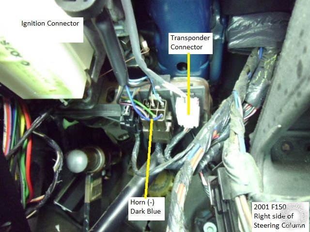
2001-2003 F-150 Remote Start w/Keyless Pictorial -- posted image.

In the above picture the transponder connector is shown.  The bypass connections

will be made on the lower harness, not the harness that comes from the ignition switch
cylinder.  Note that the wire colors change at the connectors.  Below is a photo of the
transponder connector, unplugged, with the wires marked.
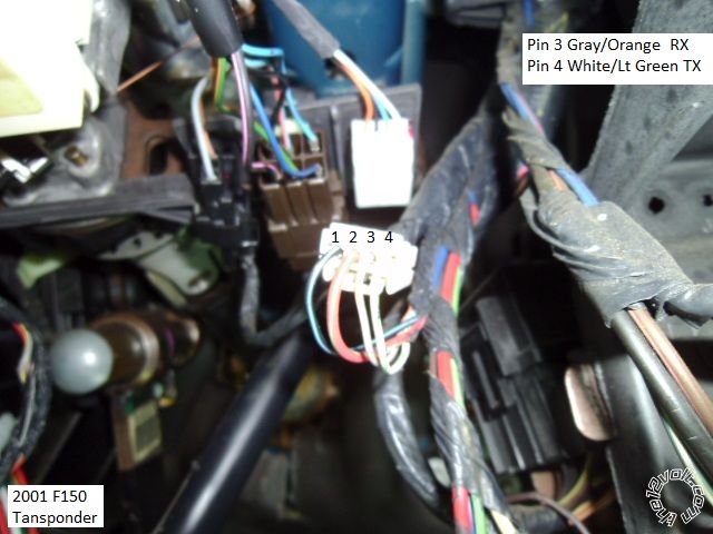
2001-2003 F-150 Remote Start w/Keyless Pictorial -- posted image.

For the Tach and Hood Pin wires, firewall pass-thru can be made at this factory grommet

located above the gas pedal.
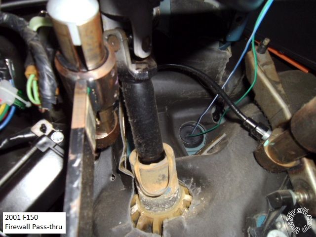
2001-2003 F-150 Remote Start w/Keyless Pictorial -- posted image.

Here is a photo of the engine side of the pass-thru :
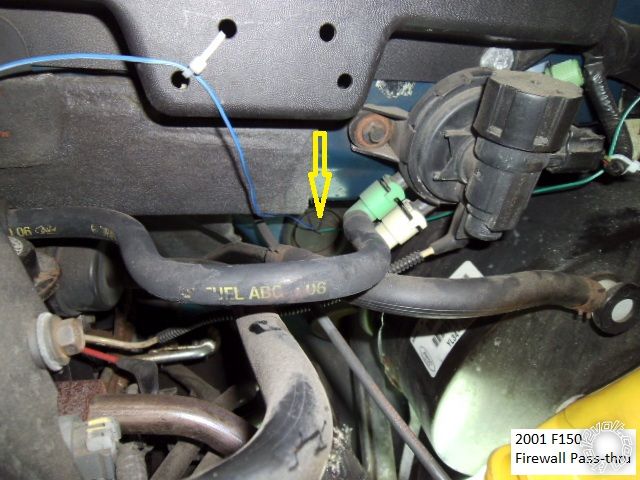
2001-2003 F-150 Remote Start w/Keyless Pictorial -- posted image.

There are several places to get a Tach signal.  The ECM is difficult due to it's location behind

the battery.  A spark coil can be used if your R/S system can learn the weak ( 0.55V AC @ idle
and 0.75V AC @ 2500 RPM ) signal.  A better choice is a F.I. which provides 1.6V AC @ idle and
2.7V AC @ 2500 RPM.  Here is a photo of the F.I. wire at the passenger side front cylinder.
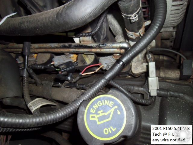
2001-2003 F-150 Remote Start w/Keyless Pictorial -- posted image.

Any quality remote start system can be used.  There is plenty of room under the dash to locate

and secure the system.  There are several good bypass modules available for this truck and
only one key is needed to program the bypass.   The 1100F bypass module is discontinued
( but available ).  Other good choices include the Fortin Key-OverRide-All and it's cousin, the
XpressKit PKALL and from iDatalink, in the Solo series, are the ADS TBSL KO and the ADS TBSL TI.

For more info on GEM Wake-Up, see DEI Tech Tip #1093 which is in this ZIP file.

https://www.the12volt.com/installbay/file.asp?ID=1076

Remember, this is just a guide.  Always test all wires with a Digital Multi Meter prior to making

your proper soldered connections.

Soldering is fun!
smokeman1 
Platinum - Posts: 1,588
Platinum spaceThis member has made a donation to the12volt.com. Click here for more info.spaceThis member has been recognized as an authority in Mobile Security and Convenience. Click here for more info.spacespace
Joined: September 14, 2009
Location: Wisconsin, United States
Posted: May 25, 2013 at 9:56 PM / IP Logged  

Once again, Real Nice Work and Pictorial....Can I adopt you?

When all else fails, Read the Instructions
Support the12volt.com Make a Donation
rheckbert3 
Member - Posts: 28
Member spacespace
Joined: November 25, 2013
Location: Massachusetts, United States
Posted: November 30, 2013 at 1:54 PM / IP Logged  
Kreg357, I used this post to install the Ultra Start and Fortin bypass in my 1999 F150 as you know because you helped me so much in my thread. Would you mind if I used these pictures and a few of my own to make a more in-depth pictorial on the12volt for 1997-2003 F150s?
Ricky
kreg357 
Platinum - Posts: 7,795
Platinum spaceThis member has made a donation to the12volt.com. Click here for more info.spaceThis member has been recognized as an authority in Electrical Theory. Click here for more info.spaceThis member has been recognized as an authority in Mobile Security and Convenience. Click here for more info.spacespace
Joined: January 30, 2009
Location: Pennsylvania, United States
Posted: November 30, 2013 at 2:15 PM / IP Logged  

Hi Ricky,

Glad this helped.  Absolutely, feel free to use any pictures you think will add to your Pictorial.  This is a popular truck and assisting other DIYer's is what this forum is all about!  2001-2003 F-150 Remote Start w/Keyless Pictorial -- posted image. 

Kreg

Soldering is fun!
ace_boy2099 
Copper - Posts: 81
Copper spacespace
Joined: January 13, 2010
Location: Florida, United States
Posted: May 30, 2014 at 11:23 AM / IP Logged  
OK, A couple questions; rheckbert3, You did your 99 F150, (ever get your walkthrough/Pictorial done?) What style? 2-door or 4 with or without RKE, etc... I have a 99 F150 SuperCab Lariat with the 4.6 (I believe it has RKE but I don't have remotes or a keypad)I'm gonna need to do this on soon and want to find out if all the wire colors and such matched up. I noticed on the Wiring Diagram/chart section they have 2 pages for the 99 F150 with a couple color differences, anyone know what those differences are? is one early 99 and the other late, or something else?
Does anyone know what kind of computer/device I could use to remove the PATS from the vehicles computer, I'd kind of rather do that if it's even possible, I'm not really looking forward to having to mess with bypass modules... unless I can find a blade module to put in the Compustar, that'd be a little cleaner.
While I'm in the dash I have to pull the cluster and re-solder the odometer so the d*** display stays on.
kreg357 
Platinum - Posts: 7,795
Platinum spaceThis member has made a donation to the12volt.com. Click here for more info.spaceThis member has been recognized as an authority in Electrical Theory. Click here for more info.spaceThis member has been recognized as an authority in Mobile Security and Convenience. Click here for more info.spacespace
Joined: January 30, 2009
Location: Pennsylvania, United States
Posted: May 30, 2014 at 5:17 PM / IP Logged  
Here is a link to rheckbert3's Pictorial : https://www.the12volt.com/installbay/forum_posts.asp?tid=135434 Doesn't look like he has
visited the site since last December.
It should be fairly easy to determine the power lock system ( Type B or Type C ) using a DMM to test the wires in the PKP.
For the added security, I would keep the PATS1 engine immobilizer system intact and use an inexpensive bypass module like the Directed
1100F that is typically available for under $20.
Soldering is fun!
rheckbert3 
Member - Posts: 28
Member spacespace
Joined: November 25, 2013
Location: Massachusetts, United States
Posted: June 11, 2014 at 11:45 PM / IP Logged  
ace_boy2099 wrote:
OK, A couple questions; rheckbert3, You did your 99 F150, (ever get your walkthrough/Pictorial done?) What style? 2-door or 4 with or without RKE, etc... I have a 99 F150 SuperCab Lariat with the 4.6 (I believe it has RKE but I don't have remotes or a keypad)I'm gonna need to do this on soon and want to find out if all the wire colors and such matched up. I noticed on the Wiring Diagram/chart section they have 2 pages for the 99 F150 with a couple color differences, anyone know what those differences are? is one early 99 and the other late, or something else?
Does anyone know what kind of computer/device I could use to remove the PATS from the vehicles computer, I'd kind of rather do that if it's even possible, I'm not really looking forward to having to mess with bypass modules... unless I can find a blade module to put in the Compustar, that'd be a little cleaner.
While I'm in the dash I have to pull the cluster and re-solder the odometer so the d*** display stays on.
Hey yes it has been a long time Kreg357, I was at school, but I am back now. Kreg357 has the link to my picturial posted above but I used a 1999 F150 5.4L 4WD (4 door - 2 suicide doors).
I would suggest that you leave the PATS system intact and buy a bypass unit. It really was'nt to hard to install and in my opion makes the whole system much more cleaner than trying to remove the PATS system (if thats even possible). I used the Fortin Bypass module I think it was like 40$ or less on ebay. Let me know if you have any more questions and I will try to be on here more now that the semester is over for the summer.
I would suggest reading through the manual to the remote start system and the bypass module as well as the color code charts on here a few times before getting started. I spent a couple of days ahead of time just researching as much as I could before I even got started.
Goodluck! (assuming you haven't finished it in that past 2 weeks)
Ricky
ace_boy2099 
Copper - Posts: 81
Copper spacespace
Joined: January 13, 2010
Location: Florida, United States
Posted: June 14, 2014 at 4:40 PM / IP Logged  
Out of curiosity, if there is currently an alarm/starter with bypass and whatnot, if I was to take that out and install a new alarm/starter and use the same bypass I wouldn't have to re-program anything right, It'd be the same as disconnecting the battery wouldn't it, or is it the alarm that stores the bypass info and the bypass just does the talking?
The old alarm would be a Compustar P2W900FM-AS (CM5000 brain/controller) and the new would be a 2W9000SS (CM6000) unit. I don't know what the existing bypass would be, the "Pros" did it and left a rats nest under the column that I now have to sort out to re-do it for a couple reasons, One being that the alarm is for some reason draining the battery (of the truck), and another is that I can't seem to find my main set of keys for the truck with the LCD Remote and instead of paying 130.00 for a new remote to an old and problematic (battery draining) system I'd just install a newer system I have laying around the place.
rheckbert3 
Member - Posts: 28
Member spacespace
Joined: November 25, 2013
Location: Massachusetts, United States
Posted: June 15, 2014 at 1:42 AM / IP Logged  
ace_boy2099 wrote:
Out of curiosity, if there is currently an alarm/starter with bypass and whatnot, if I was to take that out and install a new alarm/starter and use the same bypass I wouldn't have to re-program anything right, It'd be the same as disconnecting the battery wouldn't it, or is it the alarm that stores the bypass info and the bypass just does the talking?
The old alarm would be a Compustar P2W900FM-AS (CM5000 brain/controller) and the new would be a 2W9000SS (CM6000) unit. I don't know what the existing bypass would be, the "Pros" did it and left a rats nest under the column that I now have to sort out to re-do it for a couple reasons, One being that the alarm is for some reason draining the battery (of the truck), and another is that I can't seem to find my main set of keys for the truck with the LCD Remote and instead of paying 130.00 for a new remote to an old and problematic (battery draining) system I'd just install a newer system I have laying around the place.
The bypass is what stores the information and talks to the PATS system. When you trigger the remote start system to start the truck the remote starter tells the bypass to talk to the truck and "tricks" the truck into thinking someone has inserted a PATS key into the ignition with a code that matches the correct code in the truck. The bypass is basically just a clone of a key that sends the code to the truck when the remote starter tells it to.
I don't believe that you would have to reprogram the bypass as long as it is already programmed to the correct key. (In fact I believe some bypass systems only let you program them once for security reasons and to deter someone from stealing your bypass unit).
Ricky
mtp2 
Member - Posts: 1
Member spacespace
Joined: November 03, 2015
Posted: November 03, 2015 at 5:22 PM / IP Logged  
I have a 2003 f150 triton v8 everything in this pictorial matches mine except the transponder connector but that's all that's diffrent so far. I have my remote starter hooked up and literally EVERYTHING works except my parking lights, is there something special I need to have hooked up in order for my remote starter to be able to use my parking lights? I'd like them to at least flash when it starts so I have some sort of visual cue that it's on.
Page of 7

  Printable version Printable version Post ReplyPost New Topic
You cannot post new topics in this forum
You cannot reply to topics in this forum
You cannot delete your posts in this forum
You cannot edit your posts in this forum
You cannot create polls in this forum
You cannot vote in polls in this forum

  •  
Search the12volt.com
Follow the12volt.com Follow the12volt.com on Facebook
Friday, September 13, 2024 • Copyright © 1999-2024 the12volt.com, All Rights Reserved Privacy Policy & Use of Cookies
Disclaimer: *All information on this site ( the12volt.com ) is provided "as is" without any warranty of any kind, either expressed or implied, including but not limited to fitness for a particular use. Any user assumes the entire risk as to the accuracy and use of this information. Please verify all wire colors and diagrams before applying any information.

Secured by Sectigo
the12volt.com spacer
Support the12volt.com
Top
the12volt.com spacer