the12volt.com spacer
icon

honda civic 2012, viper 424, adsalca


Post ReplyPost New Topic
< Prev Topic Next Topic >
the12voltuser 
Member - Posts: 48
Member spacespace
Joined: May 09, 2006
Posted: June 14, 2013 at 4:25 PM / IP Logged  
Hello, I am in need of confirming wiring for my Honda Civic 2012 for remote start with the Viper 4204/Python 424 and iDataLink's ADS-AL-CA using D2D wiring. I have done my research on DBALL and have read many bad reviews about difficulty in remote starting. I have proposed the following for wiring the Honda Civic 2012, as I cannot find an official post about it on https://www.the12volt.com/installbay/vehiclewiring/1/yeard/Honda.html. Please suggest and correct:
IMMOBILIZER
First, flash to DBI-AL(DL)-HA3 (1.4). Installation Guide: http://cdncontent2.idatalink.com/corporate/Content/Manuals/DL-HA3/DBI-AL(DL)-HA3-EN_20130305.pdf
Using Installation Type 2,
Immobilizer side ~~ Car side
Pink Ignition input ~~ White 7 pin 2 Yellow @ Ignition cylinder
BROWN / Red CanH ~~ White 7 pin 4 Pink @ Ignition cylinder
BROWN / Yellow CanL ~~ White 7 pin 3 Blue @ Ignition cylinder
ORANGE / Black Key Data ~~ White 7 pin 6 LtGreen @ Ignition cylinder
Blue/Yel shorted to WHITE/ Black on immobilizer
WHITE/ red unlock ~~ unlock (-) on driver door
White lock ~~ lock (-) on driver door
Blue/red ground ~~ GND
Purple / YELLOW ground ~~ GND
Apparently, the door harness wiring is required because the car will ignore keyless signals from the bypass once started. I'm not sure whether the door harness should be controlled by the bypass or starter.
REMOTE STARTER
http://www.12voltdistributors.com/wp-content/uploads/2012/09/Viper_4204V_Installation_Guide.pdf
starter side ~~ car side
H1/1 red ~~ connected to white wire, pin 1, @ 5-Pin plug ignition switch
H3/2 RED / white ~~ same as above
H3/5 red ~~ same as above
H3/8 RED / black ~~ same as above
H1/2 black ~~ connected to chassis ground
H3/3 orange accessory output ~~ orange wire, pin 4, @ 5-Pin plug ignition switch (to heater blower 1)
H3/4 violet starter output ~~ yellow cut. to car
H3/5 green starter input ~~ yellow cut. to key side, pin 5, @ 5-Pin plug ignition
H3/7 pink/white relay output ~~ red wire, pin 3, @ 5-Pin plug ignition switch (to heater blower 2)
Connect d2d link
Set Viper to Flex Relay = ACC2 ( Menu 3, Item 8, Opt 2 )
Additional references:
http://diagrams.marktoonen.nl/index.aspx?MakeID=3&ModelID=20426
https://www.the12volt.com/installbay/forum_posts.asp~TID~133242
https://www.the12volt.com/installbay/forum_posts.asp?tid=133831&DIR=P&fid=3
Thank you in advance to the person who confirms.
kreg357 
Platinum - Posts: 7,783
Platinum spaceThis member has made a donation to the12volt.com. Click here for more info.spaceThis member has been recognized as an authority in Electrical Theory. Click here for more info.spaceThis member has been recognized as an authority in Mobile Security and Convenience. Click here for more info.spacespace
Joined: January 30, 2009
Location: Pennsylvania, United States
Posted: June 15, 2013 at 12:00 AM / IP Logged  
Assuming your Civic is auto trans...
H1/5 WHITE PIN 30 of LIGHT FLASH RELAY     Set Jumper / Fuse to (-) and connect wire to
Parking Lights Gray (-)      @ headlight switch, 12 pin plug, pin 8
I never do D2D, so not sure if D2D connects the EBrake to the Neutral Safety wire, but...
H2/2 BLACK/ WHITE (-) NEUTRAL SAFETY INPUT to chassis ground if automatic transmission
If the Civic does not have a Factory Alarm and Hood Pin then connect
H2/17 GRAY (-) HOOD PIN INPUT (NC OR NO) to the hood pin supplied in the R/S kit.
Here is some additional info on the door lock wires :
Power Lock        Blue (-)        @ driver kick, door harness, 23 pin plug, pin 16   
Power Unlock      Gray (-)        @ driver kick, door harness, 23 pin plug, pin 20
Not a big DEI person, so not sure if the R/S will automatically switch over to Engine Checking = Tach.
You should do a Tach Learn and get a good response ( after the ADS AL CA is programmed ).
Other than that, it looks good.
Soldering is fun!
the1voltuser 
Member - Posts: 13
Member spacespace
Joined: June 14, 2013
Location: California, United States
Posted: June 15, 2013 at 12:43 AM / IP Logged  
Thanks for the information Kreg. This is indeed an automatic transmission and does have factory alarm and hood pin. I have updated the wiring with your suggestions.
Immobilizer side ~~ Car side
WHITE/ red unlock ~~ Power Unlock, Gray (-), @ driver kick, door harness, 23 pin plug, pin 20
White lock ~~ Power Lock, Blue (-), @ driver kick, door harness, 23 pin plug, pin 16
REMOTE STARTER
H1/5 WHITE PIN 30 of LIGHT FLASH RELAY     Set Jumper / Fuse to (-) and connect wire to Parking Lights Gray (-) @ headlight switch, 12 pin plug, pin 8
H2/2 BLACK/ White (-) Neutral Safety input GREEN/ red - e-break switch
H2/4 Disarm - Green /Black ~~ Factory Alarm Disarm brown (driver door key unlock) driver kick, door harness, 23 pin plug, pin 14
H2/16 BROWN (+) BRAKE SHUTDOWN INPUT ~~ LT. GREEN (+) @ BRAKE PEDAL SWITCH, BLUE 4-PIN PLUG, PIN 1
H2/17 GRAY (-) HOOD PIN INPUT (NC OR NO) ~~ lt. blue - dash fuse box, 38 pin plug (C), pin 27
H2/24 Arm - Green / White ~~ Factory Alarm Arm pink (driver door key lock) driver kick, door harness, 23 pin plug, pin 23
Regarding your comment on DEI, what would you suggest as a better alternative for a remote start within a $100-200 budget.
kreg357 
Platinum - Posts: 7,783
Platinum spaceThis member has made a donation to the12volt.com. Click here for more info.spaceThis member has been recognized as an authority in Electrical Theory. Click here for more info.spaceThis member has been recognized as an authority in Mobile Security and Convenience. Click here for more info.spacespace
Joined: January 30, 2009
Location: Pennsylvania, United States
Posted: June 15, 2013 at 6:31 AM / IP Logged  
The R/S system you have chosen is fine. As with all major brands, the big difficulty is the lack of
support from the manufacturer for DIYers. They will not provide any Tech Support and will not
honor the warranty on any product not installed by an authorized Directed dealer. They also
limit availability of the full installation guides. Also, be aware that access to the iDatalink WEB site
to flash the bypass module is restricted to authorized 12 Volt professionals. If you don't meet their
qualifications, you must try to find a source that will supply a flashed bypass module.
My mention of the D2D connection stems from issues encountered ( years ago ). Just for piece of
mind, I still make all the connections between the R/S brain and the bypass module hardwired in the
W2W method. Zero issues, 100% reliability and easy to test / troubleshoot if there is a problem.
That being said, I have heard that the D2D comm is improving and you might get flawless service
that way.
Getting back to your Civic install, the ADS AL CA bypass module should handle the car's alarm
system fine thru Data ( CAN Bus ) with no extra connections between the R/S and vehicle. That
means H2/4 and H2/24 are unnecessary connections. Also the H2/17 Hood Pin and the H2/16
Brake connections can be deleted because those signals are supplied by the ADS bypass module
and are handled by the D2D interface. The only one I'm not sure about is H2/2. I think it might be the
EBrake D2D signal but you will have to test to be sure ( or go W2W and connect it that way ). Basically,
all the Red dashed wires on the ADS AL CA with DBI-AL(DL)-HA3 firmware Type 2 install diagram are
handled by the D2D connection. For me, going in W2W mode, I make all those connections and it is
more logical to understand / see what is going on. I know where the Tach signal is coming from. I know
that the Neutral Safety input is the EBrake signal from the ADS bypass module, the R/S's Brake input is
from the ADS bypass module, etc. Additionally, I can put a Digital Multi Meter on any of those wires and
verify correct operation ( Hood Pin status, for example ).
The iDatalink bypass module is a good choice. Just remember to set the Install Mode first, then program
it to the Civic. It has to be programmed and working properly to supply the R/S brain with the inputs it
needs ( Tach, Brake, Door Status, etc ) and be able to take the R/S's commands ( Lock, Unlock, etc ) and
send them on to the Civic.
Soldering is fun!
the1voltuser 
Member - Posts: 13
Member spacespace
Joined: June 14, 2013
Location: California, United States
Posted: June 16, 2013 at 10:20 AM / IP Logged  
Thanks for the extensive info. How do I link this page onto https://www.the12volt.com/installbay/vehiclewiring/1/yeard/Honda.html. so I can help others.
kreg357 
Platinum - Posts: 7,783
Platinum spaceThis member has made a donation to the12volt.com. Click here for more info.spaceThis member has been recognized as an authority in Electrical Theory. Click here for more info.spaceThis member has been recognized as an authority in Mobile Security and Convenience. Click here for more info.spacespace
Joined: January 30, 2009
Location: Pennsylvania, United States
Posted: June 16, 2013 at 1:26 PM / IP Logged  
Good question. Perhaps one of the Moderators can help on that.
Soldering is fun!
the1voltuser 
Member - Posts: 13
Member spacespace
Joined: June 14, 2013
Location: California, United States
Posted: June 23, 2013 at 11:20 PM / IP Logged  
I'm having some trouble locating the 23-pin connector for power lock. I have removed the kick panel here:
honda civic 2012, viper 424, adsalca -- posted image.
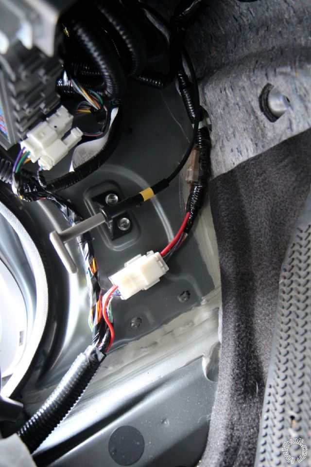
You can take a closer look at the connectors here:
honda civic 2012, viper 424, adsalca -- posted image.
kreg357 
Platinum - Posts: 7,783
Platinum spaceThis member has made a donation to the12volt.com. Click here for more info.spaceThis member has been recognized as an authority in Electrical Theory. Click here for more info.spaceThis member has been recognized as an authority in Mobile Security and Convenience. Click here for more info.spacespace
Joined: January 30, 2009
Location: Pennsylvania, United States
Posted: June 24, 2013 at 5:44 AM / IP Logged  
Try to locate the actual door harness coming in to the DKP from the door thru the flexible rubber boot. Then
follow that harness to the 23 pin connector mentioned in the wiring guides.   Sorry, I don't have a picture of
that connector.
Soldering is fun!
the1voltuser 
Member - Posts: 13
Member spacespace
Joined: June 14, 2013
Location: California, United States
Posted: June 25, 2013 at 10:57 PM / IP Logged  
Ok, I found the 23 pin connector.
honda civic 2012, viper 424, adsalca -- posted image.
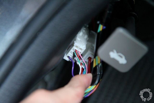
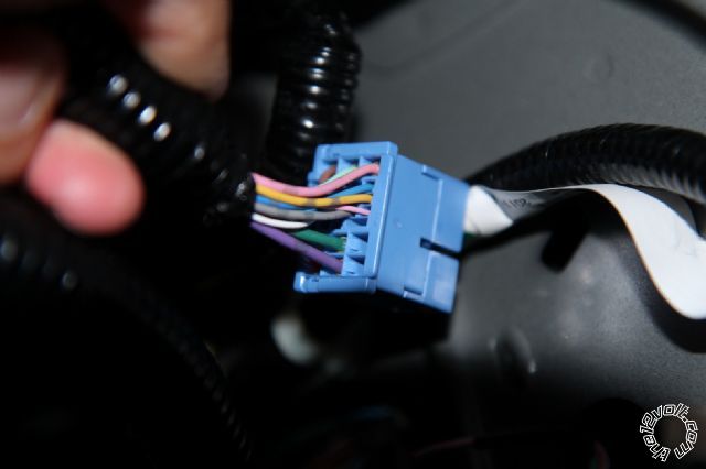
The gray wire is power unlock. However, there's conflicting information. According to http://diagrams.marktoonen.nl/index.aspx?MakeID=3&ModelID=20426, the blue wire is power lock.
According to http://www.xpresskit.com/DocumentDownload.aspx?documentid=7122&productid=461&firmwareid=2382, the pink wire is power lock (installation type 5). There is no documentation regarding pin number in idatalink's installation guide.
kreg357 
Platinum - Posts: 7,783
Platinum spaceThis member has made a donation to the12volt.com. Click here for more info.spaceThis member has been recognized as an authority in Electrical Theory. Click here for more info.spaceThis member has been recognized as an authority in Mobile Security and Convenience. Click here for more info.spacespace
Joined: January 30, 2009
Location: Pennsylvania, United States
Posted: June 26, 2013 at 5:28 AM / IP Logged  
Interesting find. I don't use the DB-ALL bypass, so I can't comment on their module or the Type 5 diagram
instructions. However, if you look closely at the included photo of the lock wires, you will see they have marked
the Gray Unlock wire and the Blue Lock wire.
I do use iDatalink modules and have found their information extremely accurate over the years.   Not to muddy
the waters but here is a link to the EVO-ALL install guide for your Civic : https://ifar.ca/download/7751/preview.html
They use the Gray and Blue wires and have a diagram of the wires location in the Blue connector ( see Connection 2 ).
I believe proper testing will identify the wire ( I would be following the iDatalink guide ) and I would be looking for
a Blue Lock wire, not Pink. If you need more info and are willing to spend a few bucks, try the Fortin WireColor
service. They list 17 wires with 20 photos for the 2012 Civic. Here is a link : http://wirecolor.com/en/
Soldering is fun!
Page of 3

  Printable version Printable version Post ReplyPost New Topic
You cannot post new topics in this forum
You cannot reply to topics in this forum
You cannot delete your posts in this forum
You cannot edit your posts in this forum
You cannot create polls in this forum
You cannot vote in polls in this forum

  •  
Search the12volt.com
Follow the12volt.com Follow the12volt.com on Facebook
Monday, May 6, 2024 • Copyright © 1999-2024 the12volt.com, All Rights Reserved Privacy Policy & Use of Cookies
Disclaimer: *All information on this site ( the12volt.com ) is provided "as is" without any warranty of any kind, either expressed or implied, including but not limited to fitness for a particular use. Any user assumes the entire risk as to the accuracy and use of this information. Please verify all wire colors and diagrams before applying any information.

Secured by Sectigo
the12volt.com spacer
Support the12volt.com
Top
the12volt.com spacer