the12volt.com spacer
icon

identifying 35 year old relay diodes


Post ReplyPost New Topic
< Prev Topic Next Topic >
toyotaguy 
Member - Posts: 22
Member spacespace
Joined: July 06, 2013
Posted: July 07, 2013 at 4:20 PM / IP Logged  
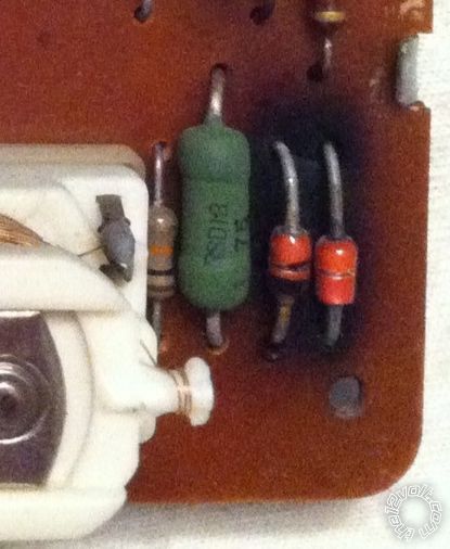
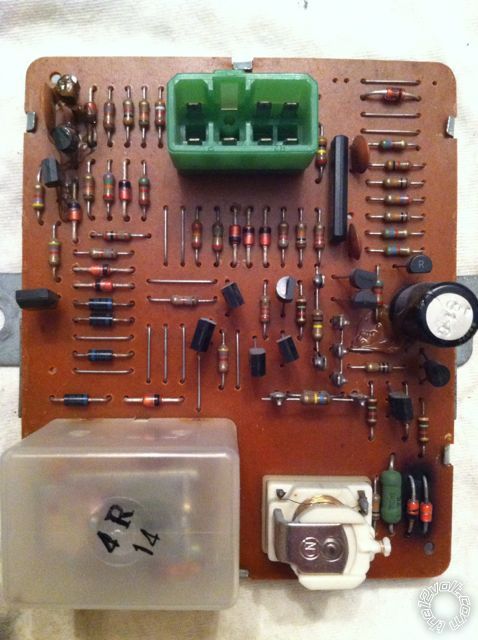
I have a "Cooling Fan Control Timer" (relay) from a 1978 Toyota FJ40 Land Cruiser that I'd love to repair than try and source a replacement for. The timer is pictured below with a closeup of the likely damaged components. My intro to EE class was in 1983 and my skills now consist of being able to use a multimeter. Any help would be greatly appreciated.
What I know: The module was made in Japan in 1978. It is from a 12V system and sits behind a 5A fuse. The only named component on the board is a cap with the "Nippon Chemi-Con" logo. The one burnt component appears to be a diode but the other - though appearing similar - has no marking to identify the cathode. Any idea what these two parts are and what I should purchase to replace them?
identifying 35 year old relay diodes -- posted image.
Ween 
Platinum - Posts: 1,366
Platinum spacespace
Joined: August 01, 2004
Location: Illinois, United States
Posted: July 07, 2013 at 5:20 PM / IP Logged  
hi,
a circuit board (trace side) would help. i'm guessing the diode(s) are for suppression control for the relay coil near them. you'll probably need to carefully remove them from the board for testing and replacement. with the localized heating there, the pads may remove with additional heat from the soldering iron.
mark
toyotaguy 
Member - Posts: 22
Member spacespace
Joined: July 06, 2013
Posted: July 07, 2013 at 6:09 PM / IP Logged  
Ween wrote:
hi,
a circuit board (trace side) would help. i'm guessing the diode(s) are for suppression control for the relay coil near them. you'll probably need to carefully remove them from the board for testing and replacement. with the localized heating there, the pads may remove with additional heat from the soldering iron.
mark
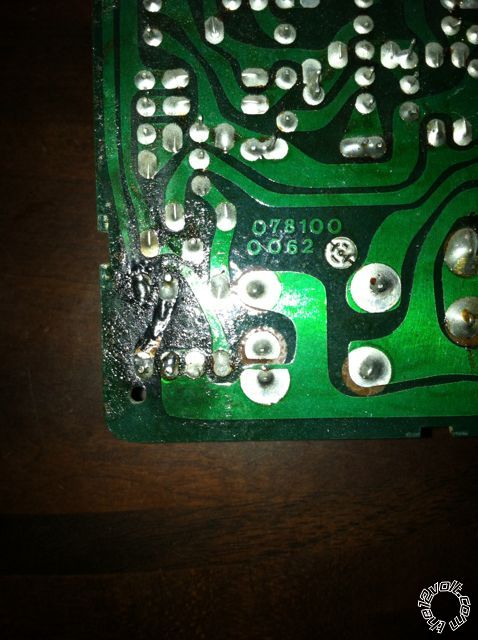
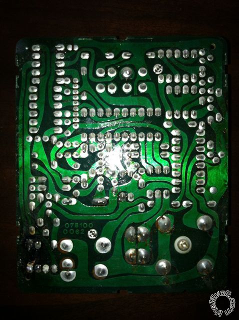
The two components were loose when I removed the board from its housing. The solder there fell off like loose grout. The trace on the back of the board has partially delaminated there also. Here are pics of the trace side.
identifying 35 year old relay diodes -- posted image.
Ween 
Platinum - Posts: 1,366
Platinum spacespace
Joined: August 01, 2004
Location: Illinois, United States
Posted: July 07, 2013 at 10:31 PM / IP Logged  
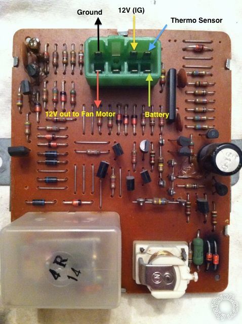
did some searching and found wiring diagram for '78 fj40. can you id the wires at the connector? (which wire is at which position). there are only five shown; ignition, battery, ground, fan output, and sensor input. should help in determining use of the diodes.
oldspark 
Gold - Posts: 4,913
Gold spacespace
Joined: November 03, 2008
Location: Australia
Posted: July 07, 2013 at 11:42 PM / IP Logged  
It's probably a Zener with series diode that some use for voltage clamping. Usually a reverse biased plain diode (IN4007 or 4007) diagonally across the 2 "end" pads will be okay especially since it's a transistor circuit.
What's the blackening on the diagonally opposite end of the PCB? (Condensation arc?)
toyotaguy 
Member - Posts: 22
Member spacespace
Joined: July 06, 2013
Posted: July 08, 2013 at 8:03 AM / IP Logged  
oldspark wrote:
It's probably a Zener with series diode that some use for voltage clamping. Usually a reverse biased plain diode (IN4007 or 4007) diagonally across the 2 "end" pads will be okay especially since it's a transistor circuit.
What's the blackening on the diagonally opposite end of the PCB? (Condensation arc?)
It's just shadowing from some brownish adhesive and my amateurish iPhone photographic skills. At first I thought a part or two had oozed its goo onto the board but all the fan controller boards have this goop on them.
oldspark 
Gold - Posts: 4,913
Gold spacespace
Joined: November 03, 2008
Location: Australia
Posted: July 08, 2013 at 9:42 AM / IP Logged  
Ah - now it does look like gunk/glue etc. IMO it looked like similar blackish carbon etc. I can only assume that the12volt's image rendering has improved (ha ha).
Does my IN400x proposed repair make sense, and do you understand how?
toyotaguy 
Member - Posts: 22
Member spacespace
Joined: July 06, 2013
Posted: July 08, 2013 at 6:13 PM / IP Logged  
Ween wrote:
did some searching and found wiring diagram for '78 fj40. can you id the wires at the connector? (which wire is at which position). there are only five shown; ignition, battery, ground, fan output, and sensor input. should help in determining use of the diodes.
Here are the connections from reading the wiring diagram and matching the wire color codes.
identifying 35 year old relay diodes -- posted image.
Ween 
Platinum - Posts: 1,366
Platinum spacespace
Joined: August 01, 2004
Location: Illinois, United States
Posted: July 08, 2013 at 6:23 PM / IP Logged  
the two diodes appear to be in series on the ignition lead...polarity protection as well as a slight voltage drop. guessing the resistor adjacent provides some isolation for the timer circuitry from the relay coil operation.
toyotaguy 
Member - Posts: 22
Member spacespace
Joined: July 06, 2013
Posted: July 08, 2013 at 8:52 PM / IP Logged  
oldspark wrote:
Ah - now it does look like gunk/glue etc. IMO it looked like similar blackish carbon etc. I can only assume that the12volt's image rendering has improved (ha ha).
Does my IN400x proposed repair make sense, and do you understand how?
I'm afraid I don't quite follow and it's certainly not your fault. Are you saying I could replace the two diodes with a single IN400x?
Page of 2

  Printable version Printable version Post ReplyPost New Topic
You cannot post new topics in this forum
You cannot reply to topics in this forum
You cannot delete your posts in this forum
You cannot edit your posts in this forum
You cannot create polls in this forum
You cannot vote in polls in this forum

  •  
Search the12volt.com
Follow the12volt.com Follow the12volt.com on Facebook
Tuesday, May 7, 2024 • Copyright © 1999-2024 the12volt.com, All Rights Reserved Privacy Policy & Use of Cookies
Disclaimer: *All information on this site ( the12volt.com ) is provided "as is" without any warranty of any kind, either expressed or implied, including but not limited to fitness for a particular use. Any user assumes the entire risk as to the accuracy and use of this information. Please verify all wire colors and diagrams before applying any information.

Secured by Sectigo
the12volt.com spacer
Support the12volt.com
Top
the12volt.com spacer