the12volt.com spacer
icon

1999-2002 Silverado Remote Start w/Keyless Pictorial


Post ReplyPost New Topic
< Prev Topic Next Topic >
wakeboarder 
Member - Posts: 1
Member spacespace
Joined: June 11, 2017
Location: Florida, United States
Posted: June 11, 2017 at 6:57 AM / IP Logged Link to Post Post Reply Quote wakeboarder
Kreg357,
I wanted to add a couple things that I needed to do to complete my 2002 Silverado 2500HD install with the Viper 5806V with the DB-ALL3 flashed with 403GM5 V4.03 firmware. I did these in addition to what you had listed.
Viper 5806V
AST13 BLACK/White (-)neutral safety/parking brake input to blue wire at parking brake switch (Viper would not allow a remote start until this wire is grounded)
AST15 Green (-) door input to Tan(-)@BCM, purple plug, B4, (This allowed programming Viper using the control center button)
Thank you for your post on this topic, it was very helpful.
All,
One issue that I am having is getting the driver priority unlock to work properly.The vehicle is wired per Kreg357's post on the 5th page of this forum with the two exceptions above. Therefore the door locks are handed D2D to the DB-All3. The DB-All3 is communicating the unlock information on the vehicle CAN line. The 1st time I hit the remote's unlock button, it unlocks all four doors. It should just unlock the driver's door. My factory remote still operates with the driver priority unlock.
I have the DB-All3 flashed to use the driver priority setting. Just in case, I ensured the Viper was programed for a single unlock pulse and for the shortest duration lock/unlock pulse.
Could it be a bug with the DB-All3? I was thinking of trying the DB-All2 to see if it would perform better.
slade725 
Member - Posts: 5
Member spacespace
Joined: March 08, 2014
Location: Louisiana, United States
Posted: September 24, 2017 at 3:14 PM / IP Logged Link to Post Post Reply Quote slade725
Where are you all putting the remote start unit? I'm going to install a prestige aps997E, evo-all and an dei 451. I don't know where to put all of this stuff, I may remove the dash and place the 997E there, the 451 in the drivers door and the evo-all under the dash. There doesn't seem like a lot of room under the column.
rheckbert3 
Member - Posts: 28
Member spacespace
Joined: November 25, 2013
Location: Massachusetts, United States
Posted: September 25, 2017 at 9:35 PM / IP Logged Link to Post Post Reply Quote rheckbert3
I put my remote start modual on its side tucked between the two vertical metal plates to the left of the steering column. I zip tied the modual to the metal bracket. I zip ties the door lock modual to a dash frame metal piece on the right of the column. Can’t quite remeber where I stuffed the bypass unit.
It is a little tight in this area on these trucks. Other people may have a better spot than I placed mine.
One thing to note that Kreg warned of is how sharp the metal brackets and metal plates are. I took 3/8? inch split loom and placed it over the edges of the metal plates and tried to run the wires over the split loom to protect them from being chaffed through.
rheckbert3 
Member - Posts: 28
Member spacespace
Joined: November 25, 2013
Location: Massachusetts, United States
Posted: September 25, 2017 at 10:00 PM / IP Logged Link to Post Post Reply Quote rheckbert3
1999-2002 Silverado Remote Start w/Keyless Pictorial - Page 12 -- posted image.
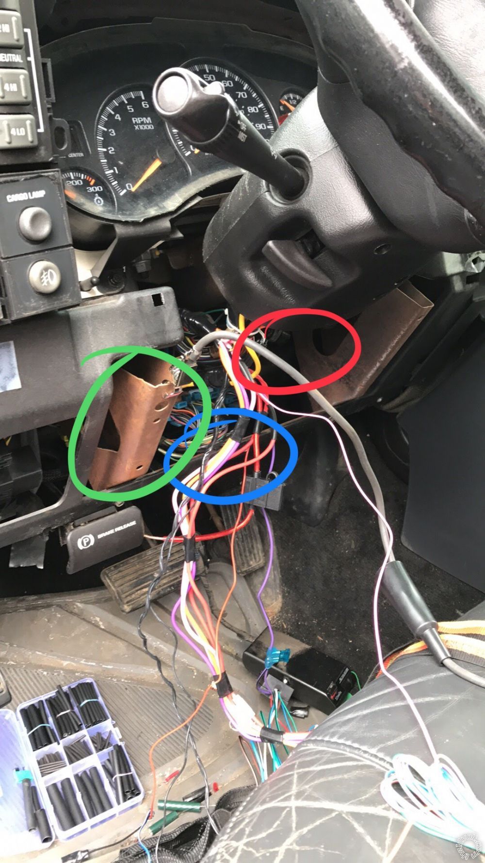
The green circle is where I put the remote start. Zip tied inside the metal bracket brace.
The blue circle is where I put the bypass module. Ziptied to the backside of that metal bar.
The red circle is where I placed the door lock unit. Somewhere up in there.
kbenny 
Member - Posts: 14
Member spacespace
Joined: October 02, 2017
Location: Texas, United States
Posted: October 02, 2017 at 9:29 PM / IP Logged Link to Post Post Reply Quote kbenny
I followed the instructions and it made the installation of an Avital 4105L, DEI 451M, and Fortin passlock SL2 very easy.
I would like to note one color difference on the parking light + wire on the BCM, mine was light blue and not the brown indicated in the instructions. It was in the same pin location and I checked it with a DMM but just in case anyone else runs into this. (2000 Silverado LT)
I have a question that some of you might be able to help me with:
I want to use the - trunk release option to activate my Rigid LED light bar.
As mine is a truck I don't have a "trunk" to release so I thought I would put it to another use.
The light bar already has a 30a relay providing power to it under the hood.
I am just looking for a way to convert the momentary trunk release - signal from the RS to a constant + signal I can tap into the existing light bar signal wire.
I have looked up the momentary - to constant + latching relay diagram found on this site but wanted to know if there is a single relay available to achieve this or any other way that would be simpler.
Any help is appreciated.
kreg357 
Platinum - Posts: 7,783
Platinum spaceThis member has made a donation to the12volt.com. Click here for more info.spaceThis member has been recognized as an authority in Electrical Theory. Click here for more info.spaceThis member has been recognized as an authority in Mobile Security and Convenience. Click here for more info.spacespace
Joined: January 30, 2009
Location: Pennsylvania, United States
Posted: October 03, 2017 at 7:44 PM / IP Logged Link to Post Post Reply Quote kreg357
While bulky, I have used that 4 relay momentary to latched relay setup with good results.   If the Rigid LED
light bar current draw is less than 10 Amps you could use mini-relays instead of the larger 30/40 Amp Bosch
style relays.   
1999-2002 Silverado Remote Start w/Keyless Pictorial - Page 12 -- posted image.
A few questions :
1. What is the current draw of the Rigid LED light bar?
2. How is the 30 Amp manual control relay under the hood triggered ( + or - from switch )?
If the current draw is below 10 Amps you could use this > $3.00 module and a direct connection to the Rigid LED
light bar. ( just one of many listed on EBay )
http://www./itm/1-Channel-Latching-Relay-Module-with-Touch-Bistable-Switch-12V-/272676896637?epid=892013745&hash=item3f7ccf3f7d:g:Ci8AAOSw7QNZlUJ4
If the current draw was over 10 Amps you could use the above module to either control the 30 Amp underhood
relay or add another external 30 Amp relay controlled by the module to directly power the lights.
Soldering is fun!
kbenny 
Member - Posts: 14
Member spacespace
Joined: October 02, 2017
Location: Texas, United States
Posted: October 03, 2017 at 9:12 PM / IP Logged Link to Post Post Reply Quote kbenny
The link you provided keeps taking me to a frontier communications search engine page.
I am considering going with the DEI 611T
It seems like the most simple and compact solution I have found yet.
There are actually 5 rigid light bars
1 24" powered by 1 30 amp relay positive trigger
3 6" powered by one 30 amp relay positive trigger
1 32" powered by one 30 amp relay positive trigger
I don't remember the amp draw on each circuit but I do know it was well below the 30 amp capacity of each relay powering it
I had a 52" rigid along with the others last year but with all the smaller ones powered on I couldn't even tell when I turned the big one on.
It was a pain not being able to go through automatic car washes and it did some very weird things aerodynamically at 70 mph and up.
Any feedback on the DEI 611T idea?
kreg357 
Platinum - Posts: 7,783
Platinum spaceThis member has made a donation to the12volt.com. Click here for more info.spaceThis member has been recognized as an authority in Electrical Theory. Click here for more info.spaceThis member has been recognized as an authority in Mobile Security and Convenience. Click here for more info.spacespace
Joined: January 30, 2009
Location: Pennsylvania, United States
Posted: October 04, 2017 at 7:22 AM / IP Logged Link to Post Post Reply Quote kreg357
The DEI 611T should accept the (-) Trunk one second output and ( wired and strapped correctly ) provide a 7.5 Amp (+)
output that could be used to turn on all the relays for all the light bars ( or just the selects ones ). A second
(-) Trunk output would then unlatch the 611T's output and the LEDs would go off. This is assuming that the light bar
relays require a (+) signal to the coil to be energized. You would need blocking diodes if connecting the to 611T to
multiple light bar relays to prevent feed back during regular switch control.
The default 611T strapping is fine. The 611T's Yellow wire would go to (+) 12 volts and the Green wire would be connected
to the R/S's (-) Trunk Output. The Brown output wire would go to the LED relay(s) (+) coil wire ( typically Pin 86 )
which should already have the (+) control signal from it's switch. If multiple relay control was desired, a 1N4001
diode would be added to each split leg of the Brown wire output.
Soldering is fun!
kbenny 
Member - Posts: 14
Member spacespace
Joined: October 02, 2017
Location: Texas, United States
Posted: October 06, 2017 at 3:14 AM / IP Logged Link to Post Post Reply Quote kbenny
Has anyone attempted to install a remote window module such as the DEI 535T with this setup?
I have spent some time looking and googling with no successful reports.
If I wanted to install a remote window module, utilizing a long press of the unlock or lock buttons to roll the windows down or up what other modules are there to look at?
kreg357 
Platinum - Posts: 7,783
Platinum spaceThis member has made a donation to the12volt.com. Click here for more info.spaceThis member has been recognized as an authority in Electrical Theory. Click here for more info.spaceThis member has been recognized as an authority in Mobile Security and Convenience. Click here for more info.spacespace
Joined: January 30, 2009
Location: Pennsylvania, United States
Posted: October 07, 2017 at 9:26 AM / IP Logged Link to Post Post Reply Quote kreg357
Should be possible. Here is the Window info :
Window Up
Driver            Dark BLUE @ MAIN SWITCH
Passenger        Light BLUE @ MAIN SWITCH
Window Down
Driver           BROWN @ MAIN SWITCH
Passenger        TAN @ MAIN SWITCH    
Test to verify wires. Here is a link to wiring with Omega AU-93 :
http://www.wiresheet.com/v2/diagrams200/211%20-%20Reversal%20Rest%20at%20Ground%20Window%20Circuit.pdf
Soldering is fun!
Page of 15

  Printable version Printable version Post ReplyPost New Topic
You cannot post new topics in this forum
You cannot reply to topics in this forum
You cannot delete your posts in this forum
You cannot edit your posts in this forum
You cannot create polls in this forum
You cannot vote in polls in this forum

  •  
Search the12volt.com
Follow the12volt.com Follow the12volt.com on Facebook
Friday, April 19, 2024 • Copyright © 1999-2024 the12volt.com, All Rights Reserved Privacy Policy & Use of Cookies
Disclaimer: *All information on this site ( the12volt.com ) is provided "as is" without any warranty of any kind, either expressed or implied, including but not limited to fitness for a particular use. Any user assumes the entire risk as to the accuracy and use of this information. Please verify all wire colors and diagrams before applying any information.

Secured by Sectigo
the12volt.com spacer
Support the12volt.com
Top
the12volt.com spacer