the12volt.com spacer
icon

compustar ft6000 as remote start


Post ReplyPost New Topic
< Prev Topic Next Topic >
freqsounds 
Copper - Posts: 289
Copper spacespace
Joined: October 17, 2008
Location: Virginia, United States
Posted: February 25, 2014 at 10:01 AM / IP Logged  
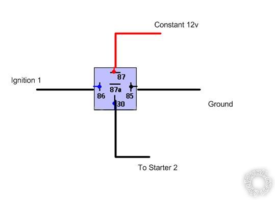
Pin 30 is the output of the relay. When pin 85 is to ground, and pin 86 receives the +12V (from the ignition1), the relay activates and connects the +12V constant source from pin 87 to pin 30 which makes ignition 2 hot.
The same goes for the starter relay.
Not sure if it makes sense the way I explained it!
No question is stupid or not worth asking. You were once a noob, right? :)
qpham504 
Copper - Posts: 51
Copper spacespace
Joined: February 25, 2014
Posted: February 25, 2014 at 11:07 AM / IP Logged  
Are you saying the ignition1 wire from the truck will trigger the relay to provide power to ignition 2, same goes for the starter wires? It took me a while to think about what you said. Let me draw out a diagram and you can confirm it for me.
qpham504 
Copper - Posts: 51
Copper spacespace
Joined: February 25, 2014
Posted: February 25, 2014 at 11:25 AM / IP Logged  
compustar ft6000 as remote start - Page 2 - Last Post -- posted image.
qpham504 
Copper - Posts: 51
Copper spacespace
Joined: February 25, 2014
Posted: February 25, 2014 at 11:26 AM / IP Logged  
My mistake thats suppose to be Ignition 2, not Starter 2.
qpham504 
Copper - Posts: 51
Copper spacespace
Joined: February 25, 2014
Posted: February 25, 2014 at 11:36 AM / IP Logged  
Also, I'm thinking in order to not blow fuses do I cut the 2nd Ignition wire from the key cylinder?
freqsounds 
Copper - Posts: 289
Copper spacespace
Joined: October 17, 2008
Location: Virginia, United States
Posted: February 25, 2014 at 12:44 PM / IP Logged  
Yea, it's a relay for ignition and a relay for starter.
No, don't cut anything or the physical key won't work! :-)
No question is stupid or not worth asking. You were once a noob, right? :)
qpham504 
Copper - Posts: 51
Copper spacespace
Joined: February 25, 2014
Posted: February 25, 2014 at 2:30 PM / IP Logged  
So following the wiring diagram that comes with the brain, I should only cut the starter1 wire ( for starter-cut relay) and continue to wire starter2 as is. The ignition wires don't need to be cut but just wire them in as you say. Most importantly an inline fuse for the constant 12v wires going to each relay. If so than I can see myself using only two additional relays.
freqsounds 
Copper - Posts: 289
Copper spacespace
Joined: October 17, 2008
Location: Virginia, United States
Posted: February 25, 2014 at 4:22 PM / IP Logged  
You can install a starter cutout, but it's not really needed since the immobilizer will do it. The truck can't be started without the correct key signal. I wouldn't go through the hassle of cutting the wires at all - except maybe on an older car without an immobilizer.
I would use 20A fuses on the relays.
No question is stupid or not worth asking. You were once a noob, right? :)
qpham504 
Copper - Posts: 51
Copper spacespace
Joined: February 25, 2014
Posted: February 25, 2014 at 5:03 PM / IP Logged  
Thanks for your help and quick responses. I now have a picture of how things need to go.
freqsounds 
Copper - Posts: 289
Copper spacespace
Joined: October 17, 2008
Location: Virginia, United States
Posted: February 25, 2014 at 9:04 PM / IP Logged  
no problem! Let us know how it goes, and don't be afraid to ask for help! Send pics if things get complicated!
No question is stupid or not worth asking. You were once a noob, right? :)
Page of 2

Sorry, you can NOT post a reply.
This topic is closed.

  Printable version Printable version Post ReplyPost New Topic
You cannot post new topics in this forum
You cannot reply to topics in this forum
You cannot delete your posts in this forum
You cannot edit your posts in this forum
You cannot create polls in this forum
You cannot vote in polls in this forum

  •  
Search the12volt.com
Follow the12volt.com Follow the12volt.com on Facebook
Monday, April 29, 2024 • Copyright © 1999-2024 the12volt.com, All Rights Reserved Privacy Policy & Use of Cookies
Disclaimer: *All information on this site ( the12volt.com ) is provided "as is" without any warranty of any kind, either expressed or implied, including but not limited to fitness for a particular use. Any user assumes the entire risk as to the accuracy and use of this information. Please verify all wire colors and diagrams before applying any information.

Secured by Sectigo
the12volt.com spacer
Support the12volt.com
Top
the12volt.com spacer